
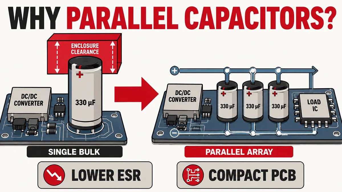
When engineering power distribution networks or designing filtering stages for DC/DC converters, relying on a single, massive bulk capacitor is often an inefficient and structurally restrictive approach. Modern hardware design heavily favors paralleling capacitors—the practice of tying multiple smaller capacitive elements across the same voltage nodes.
But why use capacitors in parallel instead of specifying a single component with the equivalent capacitance? The decision rarely comes down to simply achieving a target microfarad (\mu F) value. Instead, it is a calculated layout strategy aimed at minimizing Equivalent Series Resistance (ESR), reducing parasitic inductance (ESL), managing thermal stress, and fitting within strict PCB height constraints.
This guide breaks down the physical mechanics behind parallel capacitance, compares it directly against series topologies, and provides a real-world component data analysis to inform your next BOM (Bill of Materials) selection.
Establishing exactly what a capacitor does in a circuit provides the necessary baseline for evaluating parallel impedance reductions.
How to Add Capacitors in Parallel
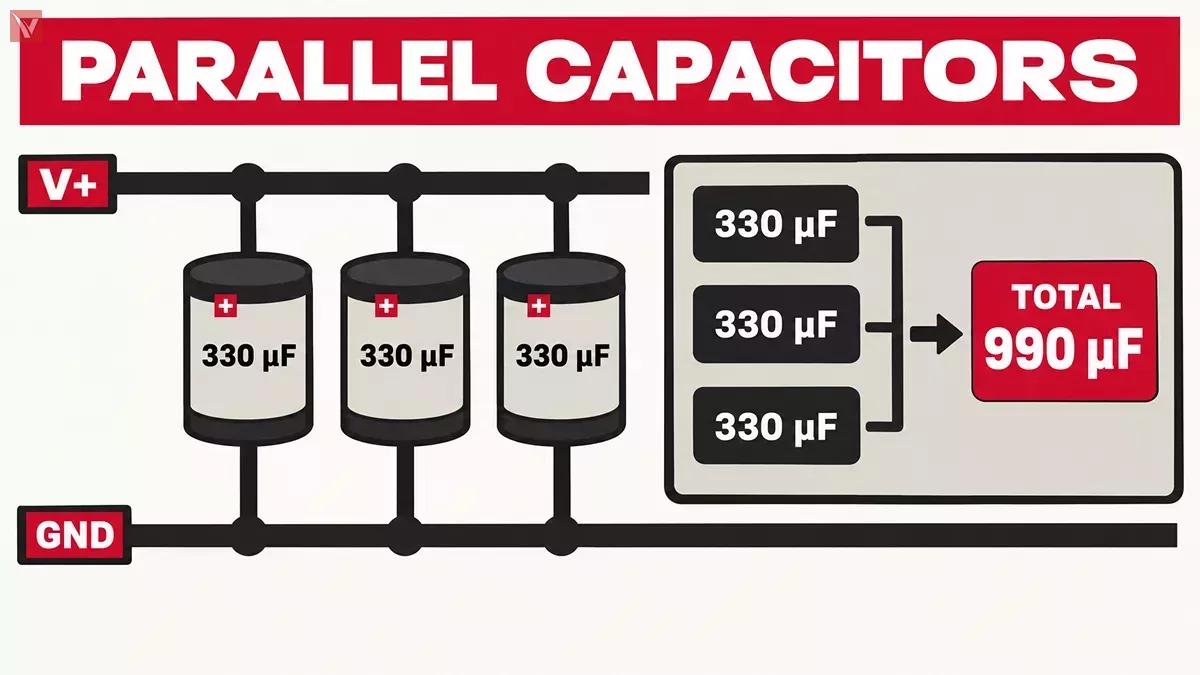
Understanding how to add capacitors in parallel requires a brief look at physical circuit connections. In a parallel configuration, the positive terminals of all capacitors connect to a single node (such as the power rail), and all negative terminals connect to another shared node (such as the ground plane).
Unlike resistors, where parallel placement decreases the total resistance, capacitors in parallel accumulate total capacitance. By connecting them this way, you are essentially increasing the total effective surface area of the conductive plates storing the electrical charge.
The governing formula is straightforward: \(C_{total} = C_1 + C_2 + C_3 + \dots + C_n\) For example, if you place three \(330\mu F\) aluminum electrolytic capacitors in parallel, the total system capacitance is exactly \(990\mu F\). This fundamental math forms the baseline for configuring robust power delivery networks.
Series vs Parallel Capacitance
Engineers constantly evaluate series and parallel configurations based on the specific stress the passive components must endure. Understanding the core difference between series vs parallel capacitance is critical for preventing catastrophic dielectric failure.
The following table summarizes the electrical characteristics of both topologies:
| Parameter | Parallel Capacitors | Series Capacitors |
|---|---|---|
| Total Capacitance | Increases (Ctotal = C1 + C2 + ...) | Decreases (1/Ctotal = 1/C1 + 1/C2 + ...) |
| Voltage Rating | Equal to the lowest-rated capacitor in the array | Increases (Sum of individual voltage ratings) |
| Equivalent Series Resistance (ESR) | Decreases (Provides multiple parallel paths) | Increases (Internal resistances add together) |
| Primary Application | DC/DC decoupling, ripple filtering, reducing PCB height | High-voltage power systems, pulse power equipment |
While a series configuration is useful for high-voltage industrial applications—such as distributing a 1000V potential across two identical 500V capacitors (which requires balancing resistors to prevent unequal voltage distribution)—it drastically increases ESR.
For standard low-voltage logic circuitry, RF filtering, and DC/DC converter decoupling, parallel structures remain the definitive standard choice because they maximize energy storage capacity while minimizing parasitic resistance.
Core Advantages of Paralleling Capacitors in Circuit Design
The shift from single bulk components to distributed parallel arrays is driven by physical and thermal limitations inherent to electronic component manufacturing.
Lowering Equivalent Series Resistance (ESR) and ESL
No capacitor is perfect. Every real-world capacitor contains Equivalent Series Resistance (ESR) and Equivalent Series Inductance (ESL) caused by the dielectric materials, internal lead wires, and terminal connections. In high-frequency applications, high ESR causes power loss, while high ESL limits the capacitor's ability to respond to rapid current transients.
When you place capacitors in parallel, you create multiple parallel pathways for the alternating current (AC) ripple. According to Ohm's Law for parallel resistance, this significantly drops the total ESR: \(\frac{1}{ESR_{total}} = \frac{1}{ESR_1} + \frac{1}{ESR_2} + \dots + \frac{1}{ESR_n}\) Lower ESR means a sharper transient response and less voltage droop when a load (like an MCU switching states) suddenly demands current.
Thermal Management and Ripple Current Distribution
Power dissipation within a capacitor is governed by the equation \(P = I^2 \times ESR\), where \(I\) is the RMS ripple current. In a high-demand DC/DC converter, a single bulk capacitor forced to absorb the entirety of the ripple current will generate significant internal heat. Heat degrades the liquid electrolyte in aluminum capacitors, directly shortening their operational lifespan.
By utilizing a parallel array, the ripple current is divided among the individual components. This achieves two critical thermal advantages:
- The individual \(I^2R\) loss per capacitor is drastically reduced.
- The combined physical surface area of multiple smaller capacitors is far greater than one large capacitor, allowing for vastly superior heat dissipation into the surrounding ambient air and PCB copper planes.
Form Factor and PCB Height Constraints
Modern hardware is aggressively miniaturized. Consider the layout constraints inside a thin LED driver profile, a wearable device, or a dense server blade. A single \(1000\mu F\) capacitor might require a 20mm vertical clearance, acting as a physical roadblock for enclosures.
Engineers bypass this by routing three \(330\mu F\) components in a parallel row. While this takes up slightly more horizontal board space (X and Y axes), it drastically reduces the Z-axis profile, keeping the PCBA flat and compliant with mechanical housing limits.
Do Capacitors in Parallel Have the Same Charge?
A frequent question encountered in schematic reviews is: do capacitors in parallel have the same charge?
The strict answer is no, unless their capacitance values are perfectly identical.
In a parallel circuit, the voltage ( \(V\)) across every capacitor is identical. However, electrical charge ( \(Q \)) is calculated by the formula \(Q = C \times V\).
Because the voltage is constant across the parallel nodes, the amount of charge stored by each capacitor is directly proportional to its capacitance. A \(10\mu F\) capacitor will store 100 times more charge than a \(0.1\mu F\) capacitor placed in parallel with it.
This physics principle is exploited daily by hardware engineers when designing wideband decoupling networks. It is standard practice to parallel a high-capacitance bulk component (like a Tantalum polymer) with a low-capacitance, highly responsive Multi-Layer Ceramic Capacitor (MLCC). The bulk capacitor handles low-frequency energy reserves (storing the bulk of the charge), while the small MLCC, boasting incredibly low ESL, filters out high-frequency RF noise.
(Note: When mixing different capacitor technologies, engineers must simulate the impedance network to avoid anti-resonance peaks—a condition where the parasitic inductance of the bulk capacitor resonates with the capacitance of the MLCC, causing an unexpected impedance spike at a specific frequency).
Single Bulk vs. Parallel Array (Panasonic FR Series)
To move beyond theoretical mathematics, let us analyze a tangible engineering scenario using data directly from the Panasonic EEU-FR Series Aluminum Electrolytic Capacitors Datasheet.
We will compare a single \(1000\mu F\) capacitor against an array of three \(330\mu F\) capacitors wired in parallel. Both setups yield an approximate total capacitance of \(1000\mu F\) at a 25V rating.
| Parameter (Tested at 100kHz / +20°C) | Design A: Single Bulk Capacitor | Design B: 3x Parallel Capacitors | Engineering Advantage of Design B |
|---|---|---|---|
| Manufacturer Part Number | 1x EEU-FR1E102 |
3x EEU-FR1E331 |
- |
| Total Capacitance | 1000 µF | 330 µF × 3 = 990 µF | Effectively identical energy storage capacity. |
| Total ESR (Impedance) | 20 mΩ | 56 mΩ ÷ 3 ≈ 18.67 mΩ | Lower total ESR minimizes I²R power losses and improves transient load response. |
| Rated Ripple Current | 2180 mA (2.18 A) | 950 mA × 3 = 2850 mA (2.85 A) | 30% greater ripple current handling. Crucial for high-demand switching converters. |
| Profile Height (Z-Axis) | 20.0 mm | 11.5 mm | 42.5% reduction in component height, enabling slimmer enclosure designs. |
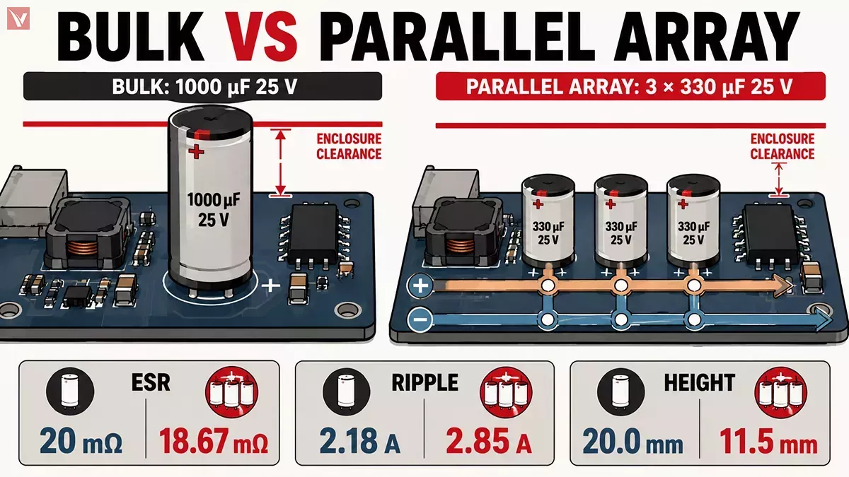
The data confirms that the parallel approach yields objectively superior electrical characteristics: it drops the internal resistance, massively increases the allowable ripple current overhead, and physically shrinks the height requirement.
BOM Optimization and Supply Chain Stability
Beyond electrical performance and PCB layout, utilizing capacitors in parallel unlocks significant supply chain advantages—a critical factor for procurement teams and production lines.
Designing a circuit around a massive, highly specific bulk capacitor often locks your production into a single manufacturer. If that specific SKU faces a supply shortage or goes End-of-Life (EOL), your assembly line stops.
Conversely, standardizing your BOM to rely on multiple smaller, widely manufactured values (such as standard \(10\mu F\), \(100nF\), or \(330\mu F\) components) provides immense flexibility.
- Reduced Feeder Complexity: Pick-and-place machines can run faster when utilizing fewer unique component reels. Using identical capacitors in parallel across various stages of the board reduces machine setup time.
- High Availability: Standard-value MLCCs and electrolytic capacitors are produced in the billions, ensuring competitive pricing and multiple alternative drop-in replacements.
When evaluating your current designs, look for opportunities to replace bulky, hard-to-source components with optimized parallel arrays. At Vigor Components, we specialize in helping engineering teams stabilize their supply chains. If you are struggling with long lead times on large capacitors, search our active inventory for readily available standard passive components to optimize your current BOM.
Frequently Asked Questions
How do I select capacitor voltage ratings for capacitors connected in parallel?
Capacitors in parallel see the same applied voltage, so every capacitor should have a voltage rating above the maximum steady-state voltage plus expected transients and derating margin. Avoid combining parts with different voltage ratings unless the lower-rated device is still safely qualified for worst-case conditions. For sourcing support, Vigor Components can help cross-check voltage rating, temperature range, case size, and lifecycle status before you release a multi-capacitor BOM.
Can I connect electrolytic, polymer, and ceramic capacitors in parallel?
Yes, but mixed capacitor technologies should be selected for complementary frequency behavior rather than simply adding capacitance. For example, an electrolytic or polymer capacitor can provide bulk energy storage, while nearby MLCCs handle high-frequency switching noise; however, engineers should verify impedance-versus-frequency curves, DC bias effects, and potential anti-resonance through simulation or measurement.
What should engineers check before replacing one large capacitor with several smaller capacitors?
Beyond matching total capacitance, verify voltage derating, ripple-current capability at the actual ambient temperature, lifetime rating, impedance across the operating frequency range, and PCB trace symmetry. The physical placement of each capacitor matters: unequal current paths can cause one part to carry more ripple current than the others. When an original bulk capacitor is constrained or obsolete, Vigor Components can help identify available multi-part replacement options based on electrical and mechanical requirements.
Can parallel capacitors cause inrush current problems during power-up?
They can, because a larger total capacitance may demand a high charging current when power is first applied. The risk depends on the source impedance, hot-plug conditions, converter soft-start behavior, upstream fuse rating, and any inrush-limiting circuit such as an NTC thermistor, resistor, MOSFET controller, or active hot-swap IC. Buyers should therefore source parallel capacitor arrays together with the relevant protection components, especially for industrial power and high-current applications.
How can an electronics distributor help manage capacitor EOL and shortage risks?
A distributor can support more than stock availability by locating authorized or traceable inventory, checking date codes and packaging, identifying form-fit-function alternatives, and consolidating multiple approved capacitor sources into a resilient AVL. For parallel-capacitor designs, this flexibility is especially useful because standardized values may offer more replacement paths than a single specialized bulk-capacitor SKU.
References
- Panasonic Industrial Devices: Aluminum Electrolytic Capacitors (Radial Lead Type) - FR Series (Source of EEU-FR1E102 and EEU-FR1E331 technical specifications).
- KYOCERA AVX: Basic Overview of Multi-Layer Ceramic Capacitors (MLCCs)
- Wikipedia: Equivalent Series Resistance (ESR) - Defining the parasitic resistance limits of real-world components.
- Murata Manufacturing: Basics of Decoupling and Power Integrity in High-Speed Digital Circuits.