
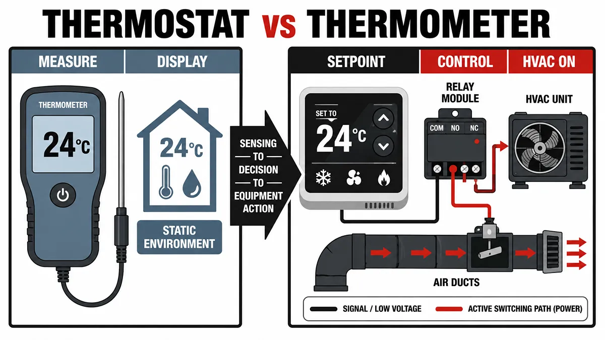
In both residential HVAC troubleshooting and industrial hardware design, the terms "thermometer" and "thermostat" are frequently used interchangeably by end-users. From an electronic engineering and system architecture perspective, they are different devices: one measures, the other controls.
The difference is not the display. It is the bill of materials and the signal path—whether the board stops at a reading, or continues on to a setpoint comparison and an actuator.
Difference Between Thermostat and Thermometer
A thermometer reports temperature. A thermostat uses that reading to decide whether heating or cooling equipment should run.
| Feature | Thermometer | Thermostat |
|---|---|---|
| Primary function | Measure ambient temperature and display it | Maintain a setpoint by switching or modulating HVAC equipment |
| Control model | Open-loop: data in, reading out | Closed-loop: sense → compare to setpoint → actuate |
| Typical output | °F / °C on an LCD, LED, or app | Control signals to a furnace, AC, heat pump, or chiller (plus a display) |
| Sensing hardware | NTC thermistor, digital temperature IC, RTD, or thermocouple | Same sensor classes, specified and filtered because the reading drives a load |
| Processing | Low-power IC or MCU for conversion and display | Deadband, minimum on/off time, schedules, equipment protection |
| Actuation | None | Relays, solid-state switches, or building-control outputs |
| Power | Coin cell or small battery in most consumer units | 24V AC in North American HVAC, plus C-wire or power-stealing on many smart units |
| If the reading is wrong | The user sees a bad number | Equipment can short-cycle, fail to start, or run too long |
| Typical use | Spot checks, logging, process monitoring | Residential and commercial climate control |
First, a thermostat always includes a temperature-sensing path. It is not a thermometer with a relay dropped onto the same board. Because the number commands a compressor or a gas valve, the sensor circuit needs noise filtering, a control deadband, and often a thermal offset for heat generated inside the enclosure.
Second, “closed-loop” does not mean “needs a 32-bit SoC.” A bimetal thermostat and a Wi-Fi thermostat close the same loop. The connected unit adds radio, UI, and scheduling; the defining hardware is still the path from sensor to load.
The sections that follow separate those two paths: measurement-only boards, then control boards, then why the two devices in the same room rarely agree.
Inside a Thermometer: The Art of Precision Measurement
When we strip away the plastic casing of a standard digital room thermometer, the internal circuitry is generally streamlined. The engineering priority is measurement accuracy, low power consumption, and stability over time—not load switching.
The heart of the device is the sensing element. Most consumer and commercial digital thermometers rely on thermistors. As ambient temperature changes, resistance follows a predictable curve. NTC thermistors (Negative Temperature Coefficient) are common indoors because resistance falls as temperature rises, which gives good sensitivity in occupied-space ranges. Some newer instruments use digital temperature ICs on I²C or a similar bus; calibration and conversion sit in the sensor package, and the host reads a finished value instead of managing a raw divider.
For an analog thermistor, the circuit uses a voltage divider and an Analog-to-Digital Converter (ADC). A small IC or low-power microcontroller converts that voltage with a lookup table or Steinhart–Hart coefficients and drives the display.
In industrial use with wider temperature extremes, designers may choose RTDs or thermocouples instead, which trade cost and signal-conditioning complexity for range and linearity. In every case, a thermometer’s hardware path ends at a display, a log, or a data interface. It does not energize HVAC control circuits.
Inside a Thermostat: The Brains of the Closed-Loop System
A thermostat must sense, decide, and switch. That third stage is what the comparison table labels “actuation,” and it is why the BOM grows. A modern smart thermostat stacks sensing, processing, and 24V switching on one product. A mechanical or basic electronic unit closes the same loop with fewer parts.
The Sensor Input
The sensing element is often a surface-mount NTC on the main PCB, or a digital temperature sensor—frequently paired with humidity on connected models. Because the reading drives equipment, the front end is built for noise immunity: hardware low-pass filtering, software averaging, and careful placement away from the radio, display, and power stage. Those parts create local heat; firmware usually applies an offset rather than treating the raw die temperature as room air.
The Microcontroller (MCU) Processing
A basic electronic thermostat only compares temperature to a setpoint and enforces a deadband. Smart units add the UI, Wi-Fi or 802.15.4 radios, and scheduling or adaptive recovery. That feature set is why many connected designs use 32-bit ARM Cortex-M class MCUs; the vendor and part number follow cost, radio integration, and supply. The controller’s job is not to print a number. It is to decide when a relay is allowed to change state.
Power and Actuation
Thermostats interface with building wiring. In North America, that is typically 24V AC from the HVAC transformer, rectified and regulated to 3.3V or 5V for logic.
Units without a C-wire may power-steal from the control loop. Stolen current must stay low enough not to hold or chat with a contactor, so the power budget is part of the control design, not an accessory.
The MCU then drives electromechanical relays or solid-state switches that close the 24V call circuits (heat, cool, fan, reversing valve). That is the hardware the thermometer never has.
Why Your Thermostat and Thermometer Show Different Temperatures
A wall thermostat at 72°F and a desk thermometer at 69°F is a common complaint. It is usually placement and control behavior, not a dead sensor.
- Deadband and display policy. The controller does not chase 72.0°F. A hysteresis band and a minimum on/off time prevent short-cycling, which wears relays and compressors. The equipment may start near 70°F and stop near 73°F. The screen may show the setpoint, a rounded value, or a filtered measurement. None of those, by themselves, prove the sensor is wrong.
- Wall micro-climate. The desk unit sees room air. The thermostat is on drywall, often over an electrical box. Exterior walls, solar gain, supply registers, and draft through the box put the thermistor in a different pocket of air than the occupied zone.
- Self-heating. Radios, backlights, and power electronics warm the enclosure. PCB layout and software offsets compensate, but the compensation is an estimate.
- Different time constants. A small handheld sensor tracks air changes faster than a wall unit coupled to gypsum. Compare the two after the room has been stable for 30–60 minutes, not in the middle of a recovery.
Check installer temperature offset, sun and airflow, and whether both instruments are actually sampling the same air before replacing parts.
Key Electronic Components for HVAC
For OEM design, the comparison table’s extra thermostat rows—filtering, deadband, isolation, power—are the actual selection problem. Accuracy on the sensor datasheet is only one line.
Sensor Accuracy and Drift
Sensors drift with thermal cycling and humidity. Tight-tolerance NTCs (e.g., ±1%) and a documented humidity/cycle history reduce field calibration issues; digital ICs move some of that burden into the package but still need a thermal path from room air to the die. The control deadband should be wider than the sensor uncertainty, or the system will chase noise.
Isolation and Safety
The user touches buttons or glass; the other side of the board switches HVAC control wiring. Isolation (optocouplers, magnetic isolators, or split power domains), creepage, surge immunity, and relay contact ratings belong in the same review as the thermistor. Residential and appliance controls are typically designed against standards such as IEC 60730, not against temperature accuracy alone.
Power Efficiency
On C-wire-less, power-stealing designs, quiescent current is a first-order constraint. Low-Iq regulators and deep-sleep MCUs exist so the board can live without holding a contactor in the wrong state. A sensor that is 0.3°F better does not matter if the power budget chatters the furnace.
Overcoming Supply Chain Challenges in Temperature Sensor Procurement
HVAC products often outlive silicon on the board. MCU families go EOL; thermistor packages get discontinued.
A last-time-buy on a setpoint controller is not like swapping a commodity resistor. A footprint change or a new core means layout, firmware, temperature calibration, EMC, safety recertification, and—on power-stealing units—contactor compatibility.
Treat sensors, MCUs, relays, and power devices as controlled parts early: flag single-sourced items, qualify an alternate before the PCN, and do not assume two NTCs are equivalent because both are 10 kΩ at 25°C. Beta value, tolerance, and package thermal behavior change the reading the control loop will act on.
Whether the need is volume NTC supply for a new smart thermostat line or allocated MCUs to keep a running product in production, a distributor with lifecycle data and a global sourcing network is what keeps that BOM buildable after the original chip is gone.