
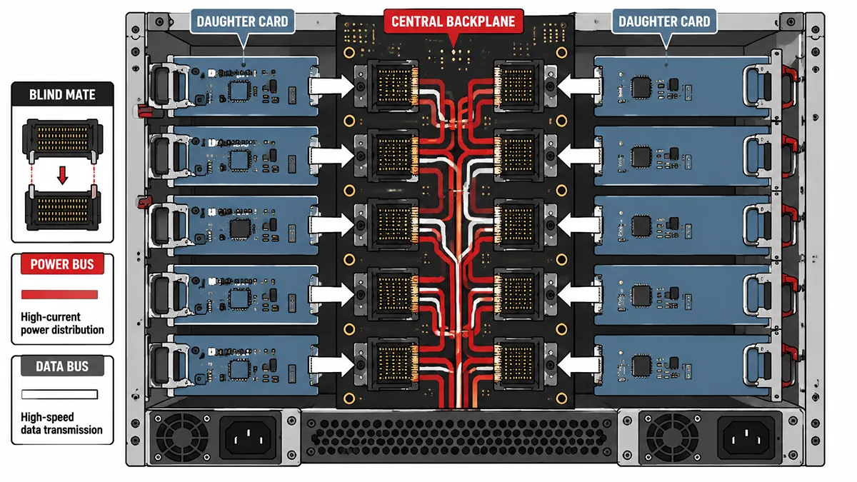
Modern servers, network switches, industrial computers, and rugged embedded systems depend on reliable board-to-board interconnects. A backplane connector is a key part of that architecture, providing the mechanical and electrical interface between plug-in cards and a backplane or midplane within a chassis. TE Connectivity describes backplane connectors as PCB interconnects used to mate printed circuit boards in right-angle, coplanar, mezzanine, and other configurations.
For engineers and procurement teams, choosing a backplane connector involves more than matching pin count or pitch. The final selection must account for the mechanical interface, termination method, electrical performance, applicable platform standard, environmental requirements, availability, and qualification process.
What Is a Backplane Connector?
A backplane connector is an electromechanical connector system, frequently categorized under the broader rectangular connector family, that links daughtercards, line cards, processor boards, I/O modules, or storage modules to a central backplane. The backplane is a PCB that distributes power and carries signal paths between modules in a chassis.
In a traditional modular system, a technician inserts a board into card guides until its mating connector engages with the connector mounted on the backplane. This arrangement can establish many signal, ground, control, and power connections in one operation.
Backplanes may be passive or active:
- A passive backplane primarily provides routing paths, connector interfaces, and power distribution.
- An active backplane may also include switching devices, management circuitry, retimers, power-control components, or other active electronics.
Backplane-based designs are common in telecom equipment, enterprise servers, network switches, industrial control systems, transportation equipment, and rugged embedded platforms. In open-standard ecosystems such as CompactPCI and VPX, published standards define specified mechanical and electrical interfaces; however, many commercial server and networking platforms remain proprietary and should not be assumed to be cross-compatible between manufacturers.
Cable Assemblies vs Backplanes
Cable assemblies and rigid backplane interconnects both have valid roles in electronic systems. A backplane is not automatically better than a cable assembly; the best choice depends on chassis size, serviceability, signal speed, routing complexity, thermal design, cost targets, and the system architecture.
| Design Factor | Cable Assemblies | Backplane Connector Systems |
|---|---|---|
| Routing Flexibility | Flexible routing between boards and around mechanical obstacles. | Fixed routing through PCB traces and defined connector locations. |
| Chassis Organization | May require cable management in dense systems. | Can create a cleaner, more repeatable internal layout. |
| Serviceability | May require individual cable disconnection and reconnection. | Allows plug-in boards or modules to mate through a defined interface. |
| High-Speed Design | High-speed twinax, active copper, and other cable technologies can support demanding links. | Requires careful connector, PCB material, trace, via, and channel design. |
| Manufacturing | Harness assembly may involve manual work or dedicated automation. | Commonly supports controlled PCB assembly methods, including press-fit for suitable products. |
| Scalability | Well suited to point-to-point and flexible layouts. | Often well suited to modular chassis with repeatable card positions. |
A rigid backplane can improve mechanical organization and make board insertion more repeatable. It can also simplify airflow planning by reducing uncontrolled cable bundles in a chassis. However, long PCB traces, vias, connector transitions, and unsuitable laminate materials can create substantial loss in a backplane channel.
For high-speed platforms, engineers should compare the performance of the complete electrical channel rather than comparing “cable” and “backplane” as isolated categories. The channel may include transmitter and receiver silicon, PCB traces, vias, connectors, cables where applicable, and equalization techniques.
Signal Integrity in High-Speed Backplanes
At high data rates, a backplane connector becomes part of a controlled transmission channel rather than a simple electrical contact. The connector transition, PCB footprint, via structure, trace length, laminate properties, and receiver equalization all affect the final signal margin.
Current high-speed connector families are designed for applications using PAM4 signaling at rates up to 112 Gb/s per lane in specified applications. For example, Amphenol’s EXAMAX2 connector system is designed to support 112 Gb/s PAM4 industry specifications and is available in nominal 85 ohm and 90 ohm differential-impedance versions for different applications.
Insertion loss
Insertion loss describes the reduction in signal amplitude as energy travels through a channel. In a high-speed backplane, loss can result from conductor loss, dielectric loss, skin effect, copper roughness, trace length, vias, and connector transitions.
A connector supplier may optimize contact geometry, dielectric materials, and differential-pair structure to reduce its contribution to channel loss. Still, a low-loss connector alone cannot guarantee acceptable system performance. Engineers should evaluate connector data together with PCB stack-up, routing length, via design, and the target protocol’s channel requirements.
Return loss and impedance discontinuities
A differential channel is designed around a target impedance, such as 85 ohms, 90 ohms, or 100 ohms depending on the interface and system requirements. Abrupt changes in geometry at pads, vias, connector pins, or mating interfaces can cause impedance discontinuities.
These discontinuities create reflections that reduce eye opening and can increase bit error rates. Connector selection should therefore include review of insertion-loss, return-loss, crosstalk, and impedance data supplied for the relevant connector configuration.
Crosstalk
Crosstalk occurs when electromagnetic coupling from one signal path affects another nearby path. Near-end crosstalk and far-end crosstalk can become critical when many differential pairs are placed in a dense connector field.
High-speed backplane connector designs may use differential-pair arrangements, ground shielding, optimized wafer structures, and controlled pin assignments to manage crosstalk. TE notes that high-speed connector development relies on signal-integrity analysis and 3D modeling of connector and footprint-via structures.
System-level verification
A connector datasheet is an essential input, but it is not a substitute for system validation. For critical designs, engineers should use simulation and measurement methods appropriate to the product stage, including:
- S-parameter review for the connector and relevant footprints
- Channel simulation using the intended PCB stack-up and trace geometry
- Time-domain reflectometry where applicable
- Eye-diagram or bit-error-rate testing
- Mechanical mating and retention testing
- Thermal, vibration, and environmental testing for the target application
For Ethernet systems, IEEE 802.3 can be an important reference for the applicable interface. However, a complete design review should also consider the specific protocol, silicon vendor guidance, platform standard, and system-level channel budget.
Common Backplane Connector Categories
These categories overlap in real-world designs. For example, legacy industrial systems often rely on standard DIN 41612 connectors, a CompactPCI system may use press-fit termination, while a VPX platform may use a high-speed connector system designed for a specific rugged embedded architecture.
Understanding these distinctions helps engineers and procurement teams avoid selecting a connector based only on its appearance, pitch, or pin count. The correct choice must also match the required mating interface, PCB footprint, electrical performance, termination process, and applicable system standard.
By Termination Method
Press-fit connectors, also called compliant-pin connectors, use terminals that are inserted into plated through-holes on a printed circuit board instead of being soldered. During insertion, the compliant section of the pin deforms elastically and creates a reliable mechanical and electrical connection with the plated hole.
This method is commonly used for large multilayer backplanes because it avoids exposing the entire board to a soldering process. It can also support controlled and repeatable assembly when the PCB hole dimensions, plating quality, insertion tooling, and connector coplanarity are properly managed.
However, press-fit is not a universal replacement for soldering. Engineers should verify the finished-hole diameter, board thickness, copper plating requirements, approved insertion force, repair procedure, and connector manufacturer's application specifications before selecting a press-fit solution.
By Connector Family and Platform Standard
Connector families and industry platforms define different mechanical, electrical, and interoperability requirements. A connector should be selected according to the relevant system standard and application rather than simply because it is described as a backplane connector.
Hard Metric and CompactPCI Connectors
Hard Metric connectors are high-density board-to-board connector families commonly used in CompactPCI systems. CompactPCI is a modular industrial computing architecture defined through PICMG specifications, while Hard Metric refers to the connector technology frequently used within that ecosystem.
These systems are often found in industrial automation, transportation, telecommunications, test equipment, and long-lifecycle embedded applications. When sourcing a Hard Metric or CompactPCI connector, confirm the applicable specification, connector position, keying arrangement, pin assignment, termination style, and mating compatibility.
VPX and VITA 46 Connector Systems
VPX is a rugged embedded computing ecosystem widely used in defense, aerospace, transportation, industrial, and other high-reliability environments. VPX systems use high-density connector technology designed to carry power, control signals, and high-speed serial data between plug-in modules and the backplane.
VPX connector selection requires careful review of the applicable VITA standard, module profile, slot profile, connector position, protocol requirements, cooling approach, and environmental conditions. A physically similar connector is not necessarily suitable for a VPX application unless its mechanical and electrical requirements have been verified.
DIN 41612 Connectors
DIN 41612 connectors and related IEC connector families remain common in legacy industrial, Eurocard, and certain VME-based systems. They are widely used for established board-to-board interconnection applications where long-term maintenance, standardized form factors, and proven mechanical performance are important.
DIN 41612 connectors should not automatically be treated as a solution for modern very-high-speed serial channels. For replacement or maintenance projects, verify the exact number of rows, contact positions, termination style, connector gender, coding, mounting hardware, plating, and mating-part compatibility.
By System Architecture
Backplane connector systems can also be described by the way boards are arranged and interconnected inside a chassis. Traditional backplane systems route signals across PCB traces between plug-in cards. This architecture is widely used in modular servers, industrial systems, networking equipment, and embedded platforms.
A midplane architecture may connect boards from both sides of a central PCB, allowing front and rear modules to interface through the same structure. This can be useful when a system requires service access from different sides of the chassis or separate front-side and rear-side functions.
In high-speed systems, an orthogonal architecture may position line cards and switch-fabric cards at approximately 90 degrees to one another. This can reduce the electrical path length compared with routing signals across a large conventional backplane. However, orthogonal designs also introduce additional mechanical, thermal, assembly, and serviceability considerations.
The final architecture should be evaluated at the system-design stage. Connector selection must support the intended signal channel, mechanical layout, cooling strategy, manufacturing process, and maintenance requirements.
Orthogonal and midplane architectures
Traditional backplane systems route signals across PCB traces from a front card to a rear connector or another card. In very high-speed systems, designers may use orthogonal or midplane architectures to shorten the electrical path and reduce the routing burden associated with a large backplane.
An orthogonal architecture typically positions cards at 90 degrees to one another, allowing a direct board-to-board interface through an appropriately designed connector system. This may reduce channel length, but it increases mechanical, thermal, manufacturing, and serviceability considerations.
The architecture decision should be made at the system-design stage. It is not simply a connector substitution.
Backplane Connectors in Storage Systems
The term “backplane” is also commonly used in storage systems, including server and NVR/DVR drive bays. However, a storage backplane should not be confused with a high-speed telecom or VPX board-to-backplane connector system.
A storage backplane typically sits behind removable drive bays and provides the power and data interface for SATA, SAS, or NVMe storage devices. Its design may include drive receptacles, power distribution, LEDs, management functions, expanders, and interfaces to the host system.
In an NVR or DVR chassis, the storage subsystem must be designed for continuous recording, drive management, thermal control, and service access. The relevant evaluation factors may include:
- Supported drive interface, such as SATA, SAS, or NVMe
- Drive-bay count and supported form factor
- Power-delivery capability and power sequencing
- Thermal design for continuously operating HDDs or SSDs
- RAID or storage-controller architecture
- Drive replacement procedure and firmware support
- Mechanical retention and vibration performance
- Compatibility with the chassis, host board, and drive carrier
Hot swapping should be described carefully. A connector may include features such as staged or sequenced mating contacts, but safe hot-swap operation is a system-level capability. It depends on the drive interface, power sequencing, controller behavior, firmware, operating system, enclosure design, and applicable platform requirements. PICMG similarly defines Hot Swap as a process for installing and removing boards without adversely affecting a running system.
Avoid claims that a connector alone guarantees zero packet loss, zero latency, or uninterrupted recording. Video-storage performance depends on the full system, including network bandwidth, switching, video encoding, processor load, storage-controller design, drive condition, firmware, and software configuration.
How to Select a Backplane Connector
A practical selection process should begin with the system requirement, not with a generic connector category.
Define the interface
Identify whether the application requires a board-to-backplane interface, a midplane interface, a direct orthogonal connection, or a storage drive-backplane interface. These architectures have different mechanical and electrical requirements.
Confirm electrical requirements
Review the target protocol, per-lane data rate, differential impedance, channel-loss budget, power requirements, grounding strategy, and signal-pair count. For high-speed systems, request the connector manufacturer’s SI documentation and evaluate it with the intended PCB design.
Confirm mechanical requirements
Check board thickness, connector height, card pitch, insertion direction, blind-mating requirements, alignment features, latching, retention hardware, mating cycles, and available chassis space.
Select the termination method
Confirm whether the application requires press-fit, solder-tail, surface-mount, or another termination method. For press-fit products, verify compatible finished-hole dimensions, PCB fabrication capability, assembly tooling, and inspection process.
Check environmental requirements
Consider operating temperature, vibration, shock, humidity, corrosion exposure, dust, and maintenance conditions. Rugged applications may require additional qualification beyond normal commercial use.
Validate supply continuity
Before release to production, review manufacturer lifecycle status, approved-vendor requirements, lead time, minimum order quantity, packaging, traceability, and availability of mating components.
Sourcing and Alternate-Part Evaluation
Backplane connectors are not interchangeable commodities. A part with a similar appearance, pitch, or pin count may still have different mating geometry, PCB footprint, press-fit-hole requirements, plating, current rating, signal-integrity characteristics, or environmental qualification.
When an original component is unavailable, an independent distributor can assist with inventory search, traceability review, lifecycle research, and potential alternate-part identification. However, any proposed alternative should be treated as a candidate for engineering validation rather than an automatic drop-in replacement.
A responsible cross-reference process should include:
- Exact manufacturer part-number verification
- Connector family and mating-interface confirmation
- Mechanical drawing comparison
- PCB footprint and finished-hole comparison
- Pinout, keying, and polarization review
- Termination-method compatibility check
- Electrical-rating and signal-integrity comparison
- Material, plating, and environmental-rating review
- Prototype build and system-level qualification
Backplane Connector Sourcing Support
Vigor Components can support sourcing requests for backplane connectors, press-fit connectors, Hard Metric connectors, VPX-related interconnects, legacy DIN 41612 parts, and associated electronic components. For a precise quotation or alternate-part review, provide the original manufacturer part number, required quantity, target application, date code requirement, and any approved-vendor or traceability requirements.
Conclusion
A backplane connector is a critical interface in modular electronic systems, but its performance cannot be evaluated in isolation. The correct product depends on the complete electrical channel, mechanical architecture, termination process, platform standard, operating environment, and supply-chain requirements.
For high-speed, high-reliability, or long-lifecycle designs, engineers should validate the connector as part of the full system. That approach reduces compatibility risk, improves signal-integrity confidence, and helps ensure that the selected interconnect is suitable for production rather than merely physically similar.