
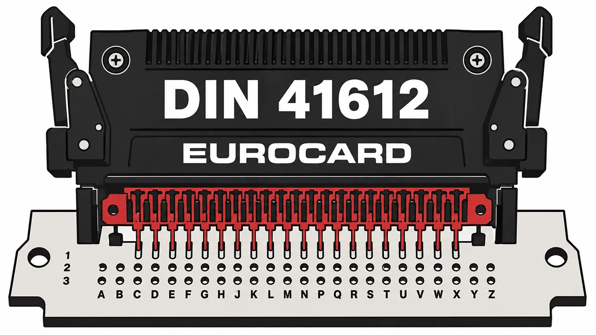
Procurement and hardware engineering teams operating in industrial control, telecommunications, and legacy transport sectors frequently face supply chain bottlenecks when dealing with standardized board-to-board interconnects. Procuring electromechanical components requires a strict alignment of physical tolerances, electrical ratings, and metallurgical properties. This text breaks down the critical technical criteria and supply chain considerations necessary for evaluating and purchasing DIN 41612 components without compromising system integrity.
What Is a DIN 41612 Backplane Connector?
A DIN 41612 connector is a standardized electrical interconnect widely deployed in rack-based electronic systems. Originally defined by the Deutsches Institut für Normung (German Institute for Standardization), the specification has been internationally recognized and superseded by the IEC 60603-2 standard.
These components facilitate the connection between plugin circuit boards (daughterboards) and a central backplane. The architecture relies on a strict 2.54 mm (0.100 inch) grid, ensuring consistent routing and signal integrity across complex backplane layouts. Operating with a standard maximum current capacity of 2A per pin and contact resistance typically below 20 mΩ, they handle both low-level signal distribution and moderate power delivery simultaneously. Modern iterations maintain backward compatibility with legacy Eurocard systems while supporting enhanced durability for continuous operation in server racks, factory automation controllers, and railway signaling equipment.
DIN 41612 Types, Contact Counts, and Pin Layouts
The physical configuration of these rectangular connectors dictates their mechanical fit and pin density. The standard defines specific form factors, categorized by letters, which determine the number of rows (a, b, and c) and the total contact count.
| Connector Type | Row Configuration | Max Contacts | Typical Application |
|---|---|---|---|
| Type B | 2 rows (a, b) | 64 | Standard signal distribution in compact Eurocard formats. |
| Type C | 3 rows (a, b, c) | 96 | High-density signal routing; standard for VMEbus architectures. |
| Type R (Reverse) | 3 rows (a, b, c) | 96 | Backplane configurations requiring male pins on the backplane rather than the daughterboard. |
| Type M (Mixed) | Variable | Mixed | Systems requiring a combination of standard signals alongside high-current, coaxial, or fiber optic contacts. |
| Type D | 2 rows (a, c) | 32 | High-voltage or high-power routing requiring greater creepage distance (5.08 mm pitch). |
Selecting the correct type requires matching not only the pin count but also the row population. For instance, a 64-pin requirement might utilize a Type C housing but leave row 'b' unpopulated, modifying the crosstalk characteristics and routing density.
How to Confirm DIN 41612 Connector Compatibility
Interchangeability is the primary advantage of standardized components. Sourcing an alternative requires validating dimensional, electrical, and mechanical parity between different manufacturers like HARTING or Amphenol FCI.
Engineers must examine the manufacturer part numbers (MPN) against the existing Bill of Materials (BOM) to verify the exact footprint. Key validation steps include:
Pitch and Grid Alignment: Verify the 2.54 mm spacing across all axes. Some proprietary variations alter the grid slightly, which will cause immediate insertion failure during assembly.
Insulator Material Ratings: Check the UL 94 V-0 flammability rating and the Comparative Tracking Index (CTI). High-temperature applications require materials like Liquid Crystal Polymer (LCP) or Glass-filled PBT.
Mating Sequence Configuration: Certain applications require Early Mate Late Break (EMLB) pins for grounding. An alternative MPN must feature the exact extended pin locations to prevent electrostatic discharge (ESD) damage during hot-swapping procedures.
DIN 41612 Termination for Backplanes and Harsh Environments
The method used to attach the connector to the printed circuit board (PCB) drastically impacts both manufacturing throughput and long-term mechanical stability under vibration.
Press-Fit Technology
Press-fit pins create a gas-tight, cold-welded joint without solder. They require precise PCB hole plating tolerances—typically utilizing Immersion Tin or ENIG finishes rather than heavy HASL. Press-fit is the preferred termination for thick backplanes where thermal mass makes wave soldering impractical. However, calculating the exact insertion force (measured in Newtons) is critical to prevent delamination of the PCB via.
Through-Hole Technology (THT)
Standard solder pins remain common for daughterboards. Procurement must confirm whether the selected part requires wave soldering, selective soldering, or pin-in-paste (THR) reflow. For automated THR processes, the plastic housing must withstand reflow oven temperatures exceeding 260°C.
Wire Wrap
Though largely obsolete in modern mass production, wire wrap terminations are still sourced for specialized test fixtures, legacy telecom switches, and prototyping racks. These feature elongated, square-profile posts designed for mechanical wire tensioning.
Sourcing DIN 41612 Connectors for Legacy Systems
Many legacy infrastructures, particularly those built around the [VMEbus standard IEEE 1014, rely heavily on 96-pin Type C connectors. When maintaining systems designed decades ago, procurement teams face severe obsolescence challenges.
Original manufacturers frequently issue Product Change Notifications (PCNs) or End of Life (EOL) declarations for low-volume variations. When sourcing for legacy maintenance:
- Identify whether the system requires specialized coding keys (small plastic inserts that prevent plugging a board into the wrong slot).
- Assess the availability of reverse-mating configurations (Type R), which were popular in 1990s telecommunication racks.
- Establish partnerships with independent distributors who maintain strict climate-controlled inventory for EOL electromechanical parts, ensuring the plastic housings have not become brittle over time.
Performance Classes, Durability, and Reliability
The IEC specification strictly defines performance levels based on mating cycles. Selecting an inadequate performance class leads to premature contact failure, increased resistance, and eventual system downtime.
Performance Class 1: Engineered for extreme longevity, guaranteeing a minimum of 500 mating cycles. These feature thick, hard-gold plating over a nickel underplate, providing maximum resistance to fretting corrosion. Required for test equipment and modular systems subject to frequent reconfiguration.
Performance Class 2: Rated for 400 mating cycles. This represents the industry standard for general industrial control systems and standard server backplanes.
Performance Class 3: Limited to 50 mating cycles. Designed for static installations where the board is inserted once at the factory and rarely removed. The plating thickness is significantly reduced.
Procurement must never substitute a Class 3 connector into a BOM that specifies Class 1 or 2, as the mechanical wear will strip the thin plating within months of active use.
Avoiding Counterfeit and Mismatched DIN 41612 Connectors
The market for mature interconnect standards contains substandard clones. These components often fail under thermal stress or exhibit erratic signal integrity due to poor alloy composition.
A rigorous quality assurance protocol is non-negotiable. At Vigorcomp, verifying electromechanical components involves strict physical and material analysis. Independent distributors must utilize X-ray fluorescence (XRF) spectroscopy to measure the exact micro-inch thickness of the gold plating. Visual inspection under high magnification is also deployed to detect misaligned pins, flash from poor injection molding, or oxidation on the terminals. Buyers should demand detailed inspection reports and traceability documentation to confirm the components meet the IEC 60603-2 specification rather than relying entirely on a supplier's verbal assurances.
What to Provide When Requesting a DIN 41612 Quote
To expedite the sourcing process and eliminate back-and-forth communication, buyers must submit highly structured Request for Quote (RFQ) documentation. Supplying an incomplete specification usually results in incorrect cross-referencing.
Ensure the RFQ includes the following data points:
Complete Manufacturer Part Number: Include all suffixes, as they often dictate the plating thickness, packaging type (tray vs. tube), and exact pin length.
Acceptable Cross-References: Explicitly state if alternative brands (e.g., swapping ERNI for Amphenol) are permitted, or if the BOM is strictly locked.
Termination Details: Specify if the manufacturing line requires press-fit, standard solder, or high-temperature reflow compatible housings.
Target Performance Class: Clearly indicate if Class 1, 2, or 3 is required.
Volume and Scheduling: Detail the immediate shortage quantity versus scheduled blanket orders, as this heavily impacts the pricing tiers for bulky mechanical parts.
Frequently Asked Questions
What is the difference between a Type C and a Type R connector?
Type C is the standard configuration where the female receptacle is mounted on the backplane and the male header is on the daughterboard. Type R (Reverse) flips this arrangement; the male header is installed on the backplane, and the female receptacle sits on the daughterboard.
Can I mix different performance classes within the same system?
While mechanically possible to mate a Class 1 receptacle with a Class 3 header, the system's overall reliability immediately drops to the lowest common denominator (50 cycles). Furthermore, mismatched plating thicknesses can accelerate wear on the higher-quality component.
What does EMLB signify in DIN 41612 applications?
Early Mate Late Break (EMLB) refers to specific pins that are physically longer than the rest. They establish an electrical connection before the standard pins during insertion, and break the connection last during removal. This sequence safely dissipates static charges and establishes ground before data lines are energized, preventing logic errors and hardware damage in hot-swappable environments.
References
- IEC 60603-2 Standard Specification
- HARTING DIN 41612 Product Data
- Amphenol FCI DIN 41612 Technical Information