
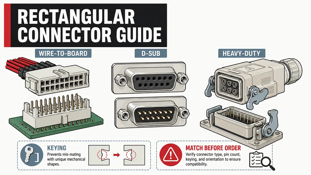
A rectangular connector is an electrical interconnect with a flat-sided housing and contacts arranged in one or more rows. It is used to carry power, control signals, data, or a combination of circuits between cables, printed circuit boards, panels, and equipment modules.
The term rectangular describes the overall connector shape rather than one specific interface standard. A compact wire-to-board header, a D-sub connector, a multi-pin sealed cable connector, and a heavy-duty industrial hood-and-insert assembly can all fall within the broader rectangular connector category.
That broad definition matters when selecting or replacing a connector. Two parts may both look rectangular and have the same number of positions, yet differ in pitch, contact gender, keying, electrical rating, termination method, mounting geometry, or mating interface.
How Rectangular Connectors Work
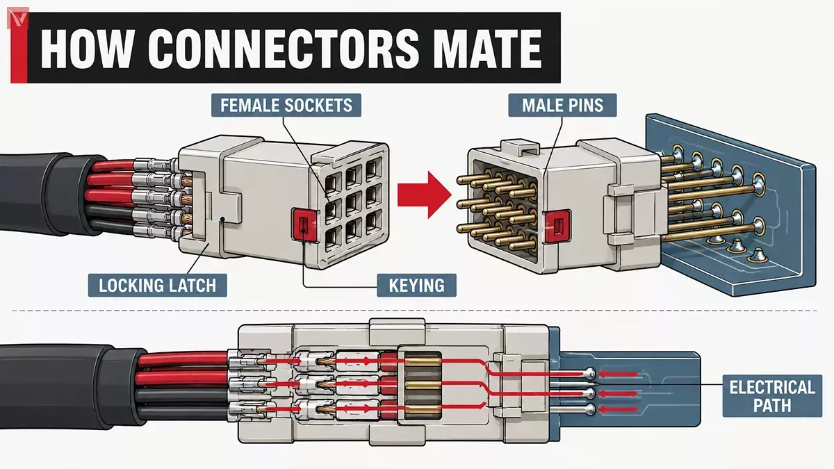
A rectangular connector creates a separable electrical connection between two parts of a system. In most designs, male contacts such as pins, blades, or tabs mate with female contacts such as sockets or receptacles. The housing holds the contacts at a defined pitch, maintains alignment, and may include polarization or keying features that prevent incorrect mating.
This separability is critical when integrating independent electron devices and circuits into a single functional chassis.
Depending on the product family, the connector can join:
- A wire harness to another wire harness
- A cable assembly to a PCB
- One PCB to another PCB
- A cable to a panel-mounted interface
- A removable equipment module to a rack or backplane
- A machine cable to an industrial control enclosure
The electrical path normally includes the conductor, terminal or contact, mating interface, and corresponding contact on the other side. For a reliable connection, the system must maintain sufficient normal force between mated contacts while controlling contact resistance, temperature rise, mechanical retention, and environmental exposure.
Common contact termination methods include:
- Crimp termination: A crimp contact is mechanically compressed onto a stripped conductor using a specified crimp tool and die.
- Solder termination: The conductor is soldered to a solder cup, solder tail, or PCB pad.
- IDC termination: Insulation displacement contacts pierce the conductor insulation and make contact without stripping the wire first.
- Screw-clamp termination: A screw secures the conductor in a terminal cavity.
- Spring-clamp termination: A spring mechanism retains the conductor without a screw.
- SMT termination: Surface-mount tails are reflow-soldered to PCB pads.
- Through-hole termination: Pins pass through plated PCB holes and are soldered on the opposite side.
The rectangular connector housing alone does not determine electrical performance. Contact material, plating, wire size, insertion force, loaded-contact count, ambient temperature, and mating quality all influence the final result.
Main Types of Rectangular Connectors
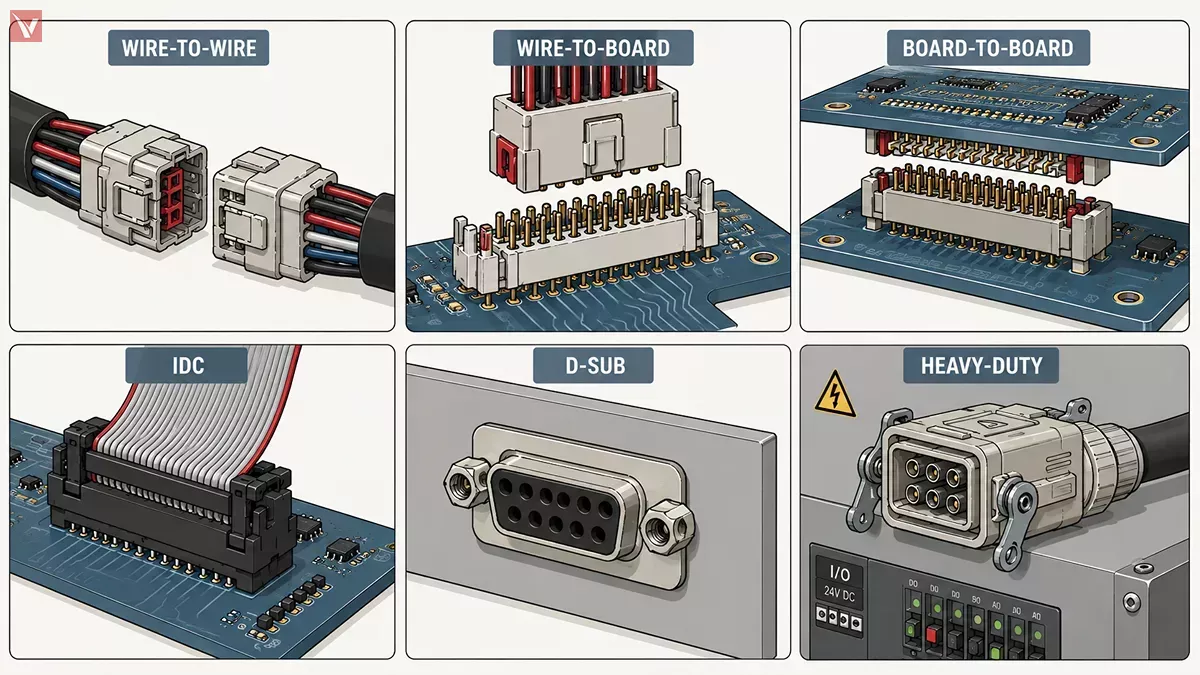
Rectangular connectors are best classified by what they connect and how they are installed. This is more useful than treating every rectangular shape as the same product category.
| Connector Type | Typical Connection | Common Applications | Key Selection Checks |
|---|---|---|---|
| Wire-to-wire connector | Cable to cable | Wire harnesses, appliances, lighting, vehicles, control wiring | Pitch, wire gauge, terminal type, contact gender, locking feature, sealing |
| Wire-to-board connector | Cable to PCB | Power supplies, embedded controllers, consumer equipment, industrial electronics | Header orientation, PCB footprint, pitch, current rating, mating height |
| Board-to-board connector | PCB to PCB | Compact electronic assemblies, daughtercards, modular control boards | Stack height, alignment, pin count, plating, impedance requirements |
| IDC connector | Ribbon cable to PCB or cable | Internal equipment wiring, legacy electronics, flat-cable assemblies | Ribbon cable pitch, conductor count, keying, strain relief, contact orientation |
| D-sub connector | Cable or panel I/O | Serial communication, test equipment, industrial control, legacy data interfaces | Shell size, contact density, gender, mounting hardware, termination style |
| Heavy-duty rectangular connector | Panel to cable or machine module | Automation equipment, robotics, machinery, cabinets, power distribution | Insert, hood, base, contacts, cable gland, latch, assembled protection rating |
| High-density or rack connector | Board, panel, or module interface | Telecom equipment, aerospace systems, rack-and-panel assemblies | Pinout, guide pins, float mount, mating force, shielding, signal integrity |
Wire-to-Wire Connectors
Wire-to-wire rectangular connectors join two cable assemblies without requiring a PCB. They are common in harness systems where a machine, appliance, vehicle subsystem, or lighting assembly needs a removable connection.
Important features often include:
- Positive latching to resist accidental unmating
- Polarization to prevent reversed insertion
- Crimp contacts matched to a defined wire-size range
- Terminal position assurance features that help retain contacts in the housing
- Seals, grommets, or rear boots for dust and moisture protection
For a replacement, wire gauge and terminal style are as important as the housing shape. A contact designed for 22 AWG wire should not be crimped onto a much larger conductor simply because it can physically enter the cavity.
Wire-to-Board Connectors
Wire-to-board connectors join a cable assembly to a printed circuit board. The board-side component is usually called a header, while the cable-side component may be called a receptacle housing, plug housing, or socket housing.
They are widely used in:
- DC power input assemblies
- Internal signal harnesses
- Battery connections
- Control boards
- Sensor and actuator interfaces
- Display and user-interface modules
Board-side headers may be vertical or right-angle. They may use through-hole tails for mechanical strength or SMT tails for automated assembly and reduced PCB drilling. Some series also use locating pegs, retention posts, or board locks to improve placement stability during soldering and service.
Board-to-Board Connectors
Board-to-board connectors directly join two PCBs. They are commonly used where a main board must connect to a daughtercard, display board, RF module, expansion card, or compact internal assembly. Standardized variants, such as DIN 41612 connectors, are frequently specified in these architectures to guarantee mechanical alignment and mating reliability.
Selection should account for:
- Board-to-board spacing or stack height
- Parallel, perpendicular, or mezzanine orientation
- Number of mating cycles
- Tolerance to board misalignment
- Contact plating and corrosion resistance
- Required signal bandwidth and impedance control
A high pin count does not automatically mean a connector is suitable for high-speed data. Interfaces carrying fast differential pairs may require a connector series with controlled impedance, defined return paths, and validated insertion-loss and crosstalk performance.
IDC Connectors
IDC, or insulation displacement connector, systems are commonly associated with ribbon cable and flat cable assemblies. Rather than using a stripped conductor and crimp barrel, the metal contact displaces insulation to reach the conductor.
IDC systems can simplify assembly, but compatibility depends on the exact cable construction. Before ordering, confirm:
- Conductor pitch
- Wire gauge or conductor diameter
- Solid versus stranded conductor compatibility
- Number of positions
- Keyed position or blocked contact location
- Strain-relief arrangement
- Cable exit direction
A keyed IDC connector is especially important when a reversed ribbon cable could damage a board or cause incorrect signal routing.
D-Sub Connectors
D-subminiature connectors, often shortened to D-sub, use a characteristic D-shaped metal shell with contacts arranged in rows. They remain common in industrial equipment, instrumentation, serial interfaces, test systems, and legacy communication hardware.
Typical D-sub variants include:
- Standard-density D-sub connectors
- High-density D-sub connectors
- Mixed-layout power and signal D-sub connectors
- Filtered D-sub connectors
- Panel-mount and cable-mount versions
- Crimp, solder-cup, PCB, and press-fit versions
When replacing a D-sub connector, verify the full configuration rather than simply ordering “a 25-pin D-sub.” Shell size, contact density, contact gender, mounting hardware, connector orientation, and termination style must match the intended mating half.
Heavy-Duty Rectangular Connectors
Heavy-duty rectangular connectors are typically used where cables must be disconnected and serviced in industrial environments. Unlike a small board connector, a complete heavy-duty assembly may include separate inserts, hoods, bases, contacts, cable glands, locking levers, gaskets, and protective covers.
These systems are often used for mixed power, control, and signal wiring in:
- Industrial control cabinets
- Robotics cells
- Factory machinery
- Motor and drive systems
- Railway and transportation equipment
- Renewable-energy equipment
- Modular production lines
Some heavy-duty systems use modular frames that can combine power contacts, signal contacts, pneumatic modules, fiber interfaces, or data modules in one enclosure. This can simplify machine interfaces, but only when the layout is properly designed for electrical separation, service access, and cable routing.
High-Density and Rack Connectors
High-density rectangular connectors are used where many circuits must fit into limited panel or PCB space. Multi-row arrangements can support high contact counts, and designs with guide pins or floating mounts can support blind mating in rack-and-panel equipment.
Common examples include:
- Micro-D connectors
- Nano-D connectors
- ARINC-style avionics connectors
- Backplane connectors
- Rack-and-panel connectors
- High-density board-level connectors
These products may be used in aerospace, telecom, defense, data systems, laboratory instruments, and compact control equipment. However, their suitability for high-speed or harsh-environment use depends on the exact series and configuration, not merely on the connector’s rectangular shape.
Connector Parts and Mating Hardware
Not every rectangular connector is sold as a complete, ready-to-install pair. This is one of the most common causes of ordering mistakes.
A small wire-to-board assembly may only require a header, a receptacle housing, and loose crimp contacts. A heavy-duty industrial system may require multiple items that are ordered separately.
Board-Level Connector Parts
For PCB-level connector systems, the required components may include:
- PCB header
- Receptacle or plug housing
- Male or female crimp terminals
- Terminal retainer
- Polarization feature
- Strain-relief accessory
- Dust cap or protective cover
- Mating cable assembly
Always confirm whether contacts are preloaded in the housing. Many connector housings are supplied empty and require separate terminal selection.
Heavy-Duty Connector Parts
A typical heavy-duty rectangular connector assembly can include:
| Component | Primary Function | Replacement Risk |
|---|---|---|
| Male or female insert | Holds the contacts in a defined arrangement | Incorrect contact count, gender, or terminal style prevents mating |
| Hood | Protects the cable-side assembly and provides cable entry | Wrong entry direction or thread size can interfere with installation |
| Base | Mounts to a panel, bulkhead, or equipment enclosure | Panel cutout, latch style, and mounting pattern may not match |
| Contacts | Carry current or signals through the insert | Wire range, plating, and crimp dimensions must be correct |
| Cable gland | Secures and seals the cable entry | Incorrect cable diameter range can compromise strain relief or sealing |
| Gasket or seal | Supports environmental protection at the mounting interface | Omission can reduce the protection of the assembled system |
Do not assume a hood, base, or insert from one manufacturer will mate with a visually similar part from another manufacturer. Intermateability should be confirmed by the manufacturer’s documentation or by a controlled physical verification process.
Common Uses Across Equipment
Rectangular connectors are used across a wide range of electrical and electronic equipment because they can accommodate many contact arrangements, mounting styles, and circuit types.
Industrial Equipment
In industrial systems, rectangular connectors often support modular wiring between control cabinets and machines. A single interface may carry:
- 24 VDC control power
- Sensor and actuator signals
- Motor feedback circuits
- Ethernet or fieldbus communications
- Safety-related circuits
- Auxiliary power lines
For these installations, serviceability may be as important as electrical performance. A connector that allows a cable harness to be disconnected quickly can reduce maintenance time when replacing a motor, sensor module, control panel, or machine subassembly.
Electronics and Embedded Products
In compact electronic products, wire-to-board and board-to-board rectangular connectors are used for internal interconnects. Typical functions include battery connections, display interfaces, fan wiring, camera modules, daughtercards, and low-voltage power distribution.
Key concerns include:
- PCB space
- Low-profile height
- Assembly orientation
- Mating-cycle requirement
- Contact reliability under vibration
- Correct polarity
- Automated production compatibility
Transportation and Outdoor Systems
Vehicles, traffic equipment, renewable-energy products, marine devices, and outdoor installations may use sealed rectangular cable connectors. Environmental protection depends on the final mated assembly, including the housing, seals, cable entry, strain relief, and mounting method.
For outdoor use, check more than an IP rating printed on a catalog page. Verify the rating applies to the exact mated configuration, cable diameter, cable gland, and installation orientation.
Test and Laboratory Equipment
D-sub connectors, board-level headers, and multi-pin cable connectors are frequently used in test fixtures, laboratory instruments, educational equipment, and prototype systems.
These users often need parts that are:
- Easy to identify
- Available in small quantities
- Serviceable without specialized equipment
- Compatible with existing cables or panel cutouts
- Suitable for repeated mating during testing
For prototype work, selecting a connector family with readily available mating halves, contacts, backshells, and tools can avoid delays later in the build process.
Rectangular or Circular Connector?
Rectangular and circular connectors are not direct substitutes in every application. The correct choice depends on contact count, available mounting space, cable routing, environmental requirements, mating method, and the required interface standard.
| Consideration | Rectangular Connector | Circular Connector |
|---|---|---|
| Contact arrangement | Contacts are commonly arranged in rows or grids | Contacts are arranged around a circular interface |
| Panel use | Often efficient for flat panel layouts and high contact counts | Often compact for individual cable entry points |
| Modularity | Some industrial systems support configurable inserts or modules | Typically selected from fixed insert arrangements within a series |
| Blind mating | Can use guide pins, float mounts, and rack-and-panel hardware | Available in selected families but depends on the coupling system |
| Typical decision point | Useful where contact density, panel layout, or mixed circuits are priorities | Useful where a specified circular family better suits cable routing or environmental requirements |
Rectangular connectors are often attractive for high-density or modular layouts because flat-sided housings can use panel space efficiently and support multi-row contact arrangements.
However, a circular connector may still be the better choice when a system already uses a qualified circular interface, when cable routing requires a particular coupling geometry, or when the specified circular family better meets sealing, vibration, or mechanical requirements.
How to Identify a Replacement
Do not identify a replacement connector from a front-view photograph alone. A connector that appears similar may have a different pitch, keying arrangement, terminal design, shell size, or mating geometry.
Before searching for a replacement, collect the following information:
- Complete manufacturer part number, including suffixes
- Brand name, series marking, or molded code
- Clear photos of the front mating face and rear termination side
- Number of positions and number of populated contacts
- Contact gender: pin, socket, tab, blade, or mixed configuration
- Keying or polarization pattern
- Contact arrangement and row count
- Housing pitch and insert dimensions
- Panel cutout and mounting-hole spacing
- Cable entry direction: top entry, side entry, straight, or angled
- Termination style: crimp, solder cup, screw, IDC, SMT, or through-hole
- Wire size and insulation diameter, where relevant
- Mating connector part number, if known
- Required electrical rating and environmental protection level
- The two most important rules are simple:
- The same pin count does not prove compatibility.
- The same outside shape does not prove that two connectors will mate.
For a cable-side connector, confirm whether you need only the housing or a complete assembly that includes contacts, a hood, cable gland, and strain-relief hardware. For a PCB connector, confirm both the mating interface and the board footprint before ordering.
Checks Before You Order
A connector must fit mechanically, mate correctly, and operate safely under its intended electrical and environmental conditions. The following checks help prevent avoidable ordering errors.
Basic Compatibility Checks
For any rectangular connector order, confirm:
- Manufacturer and product series
- Part number and revision suffix
- Contact count and contact gender
- Contact layout and keying
- Mating connector compatibility
- Mounting style and dimensions
- Termination method
- Required accessory components
Electrical Checks
For powered circuits, review:
- Rated voltage
- Current rating per contact
- Number of simultaneously loaded contacts
- Wire gauge range
- Contact resistance
- Temperature rise and derating information
- Creepage and clearance requirements
- Required approvals or compliance documents
A single-contact current rating should not be treated as the guaranteed current capability of every position in a fully populated connector. Adjacent energized contacts, high ambient temperature, limited airflow, and undersized conductors can increase temperature rise.
Mechanical and Environmental Checks
Where the installation is exposed to vibration, dust, moisture, outdoor conditions, or repeated service, also verify:
- Mating-cycle rating
- Latching or locking method
- Cable strain relief
- Vibration and shock performance
- Operating temperature range
- IP rating of the complete mated assembly
- Gasket and cable-gland compatibility
- Corrosion resistance of contacts and housing
- Shielding and grounding requirements
For high-speed or sensitive signal interfaces, ask whether the connector family provides controlled impedance, shielding features, or S-parameter data. High-speed performance must be validated at the connector-system level rather than inferred from the connector’s physical size.
Sourcing Rectangular Connectors
Rectangular connector requirements range from a single replacement plug to a recurring production requirement. In either case, accurate identification is the fastest route to a usable part.
At Vigor Components, we support sourcing for maintenance work, repairs, prototypes, equipment upgrades, and ongoing production. The complete manufacturer part number is the best starting point. When that number is unavailable, detailed photos and configuration information can make the search far more accurate.
For a meaningful request, provide:
- Manufacturer name and full MPN, if available
- Photos of both mating faces and the rear termination area
- Pin count, contact gender, and keying
- Panel dimensions or PCB footprint information
- Wire size and termination method
- Cable-entry direction and enclosure requirements
- Voltage, current, and environmental conditions
- Whether you need an exact part or are open to a reviewed alternative
We can help distinguish between an exact-match request and an alternative that needs further mechanical or electrical review. For multi-part assemblies, it is also important to confirm whether the order includes all required items: inserts, contacts, hoods, bases, cable glands, seals, and protective accessories.
Our online ordering platform provides a more direct way to check availability and place an order after the required configuration has been confirmed. Whether the requirement is a single replacement connector or a larger recurring order, correct identification should come before price comparison.
Frequently Asked Questions
Is a D-sub connector a rectangular connector?
Yes. A D-sub uses a D-shaped shell with contacts arranged in rows, so it belongs to the broader rectangular connector category. Its shell size, contact density, gender, and termination type must still be matched.
Can I replace a rectangular connector with one that has the same pin count?
Not necessarily. Pin count does not confirm pitch, keying, contact gender, contact arrangement, current capability, mounting dimensions, or mating compatibility.
Do rectangular connectors always use pins and sockets?
No. Many use pin-and-socket contacts, but others use blades, tabs, spring contacts, IDC contacts, solder tails, or specialized high-speed contact systems.
Do I need to order contacts separately?
It depends on the series. Some connectors are supplied with preloaded contacts, while many crimp-style and heavy-duty systems require contacts to be selected and ordered separately.
Can rectangular connectors be used outdoors?
Some can, but outdoor suitability depends on the complete mated assembly. The housing, seals, cable gland, mounting method, cable diameter, and stated protection rating must all be considered.