
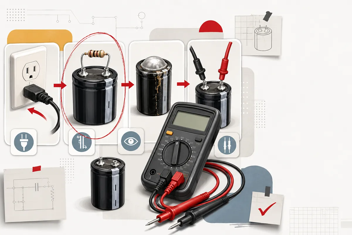
Capacitors are fundamental passive components in modern electronics, responsible for critical functions such as energy storage, voltage filtering, signal decoupling, and noise suppression. Despite their robust design, capacitors are susceptible to degradation over time due to thermal stress, voltage spikes, and dielectric aging. When an electronic control board, power supply, or motor drive fails, a degraded or blown capacitor is frequently the primary suspect.
Accurate diagnostic procedures are essential for any hardware engineer, field technician, or procurement specialist attempting to minimize system downtime. While advanced LCR meters offer granular data regarding Equivalent Series Resistance (ESR) and dissipation factors, a standard digital multimeter (DMM) remains the most accessible and practical tool for frontline troubleshooting.
This technical guide outlines the precise engineering methodologies required to test capacitor with multimeter effectively. By following these standardized protocols, you can definitively identify component failure, ensure workplace safety, and streamline the subsequent procurement of replacement parts.
Crucial Safety Steps to Discharge a Capacitor
Working with electronic components requires strict adherence to safety protocols, especially when handling high-voltage capacitors found in power supplies, motor start circuits, and HVAC systems. A capacitor functions as a temporary battery and can retain a lethal electrical charge long after the main power source has been disconnected. Before any diagnostic tools are applied, complete physical discharge is non-negotiable.
Attempting to test a charged capacitor will not only yield grossly inaccurate multimeter readings but can also permanently destroy the multimeter's internal fuse and circuitry. More importantly, it poses a severe risk of electric shock to the operator.
The industry-standard method for safely discharging a capacitor involves using a high-wattage bleeder resistor rather than shorting the terminals with a screwdriver. Shorting terminals directly creates a rapid discharge transient that can weld the tool to the contacts, damage the capacitor's internal connections, and generate dangerous sparks.
To safely discharge the component:
- Ensure the equipment is entirely unplugged from the mains power supply.
- Select a suitable resistor, typically a 20kΩ to 50kΩ wire-wound resistor rated for at least 5W to 10W.
- Using electrically insulated alligator clips, connect the resistor across the two terminals of the capacitor.
- Allow sufficient time for the voltage to drop. The time required is governed by the RC time constant equation
 A standard practice is to wait for at least five time constants
  to ensure the voltage has decayed to less than 1% of its initial value.
 - Verify the discharge is complete by setting your multimeter to the DC voltage setting and measuring across the terminals. The reading should be 0V.
Visual Fault Signs Before the Multimeter Test
Before deploying electrical instrumentation, a comprehensive visual inspection can often diagnose a catastrophic component failure immediately. Capacitors, particularly aluminum electrolytic types, exhibit distinct physical symptoms when they experience thermal runaway, overvoltage conditions, or end-of-life degradation. Skipping visual inspection can lead to wasted time testing a component that is visibly compromised.
| Visual Symptom | Typical Capacitor Type | Underlying Engineering Cause | Diagnostic Conclusion |
|---|---|---|---|
| Bulging or Domed Top | Electrolytic | Internal gas generation due to excessive heat or dielectric breakdown. | Defective. Immediate replacement required. |
| Leaking Electrolyte | Electrolytic / Supercapacitors | Seal degradation causing liquid dielectric to escape. | Defective. Risk of PCB corrosion. |
| Cracked Outer Casing | Ceramic / Film / Tantalum | Mechanical stress or thermal shock leading to fracture. | Defective. Likely internal open/short. |
| Scorched or Burn Marks | All Types | Catastrophic short circuit causing combustion. | Defective. Check trace wiring. |
If any of the structural anomalies listed in the table above are observed, multimeter testing is entirely redundant. The component has failed and must be desoldered and discarded. If the component appears physically pristine, you may proceed with electrical verification.
Accurate Measurements via the Capacitance Mode
For digital multimeters equipped with a dedicated capacitance measurement function, this approach yields the most reliable diagnostic data. The capacitance mode actively measures the component's ability to store an electrical charge and displays the result in Farads (typically microfarads, µF, or nanofarads, nF).
To ensure high-fidelity measurements, the capacitor must be isolated from the broader circuit. Measuring a capacitor while it is fully soldered into a printed circuit board (PCB) will introduce parasitic capacitance and parallel resistance from adjacent ICs and passive components, skewing the DMM's calculations. For through-hole components, desolder at least one lead. For Surface Mount Devices (SMD), complete removal from the pad is recommended.
Execution Steps:
- Discharge the capacitor fully as outlined in the safety guidelines.
- Turn the multimeter dial to the Capacitance symbol (often indicated by a capacitor circuit icon: -||-).
- Connect the test probes to the component terminals. For polarized components like aluminum electrolytic and tantalum capacitors, strict adherence to polarity is required: connect the red probe to the positive terminal (the longer lead) and the black probe to the negative terminal (indicated by a stripe on the casing).
- Allow the multimeter several seconds to inject a known current, measure the voltage rise rate, and compute the final capacitance value.
Evaluate the reading against the nominal value printed on the capacitor's casing while accounting for the manufacturer's tolerance. For instance, a 1000µF capacitor with a ±20% tolerance is considered perfectly healthy if the multimeter displays any value between 800µF and 1200µF. If the reading falls significantly below this threshold, the dielectric has deteriorated, and the component is out of specification.
Health Check Alternative Under the Resistance Setting
Not all multimeters feature a dedicated capacitance measurement mode. In such scenarios, the resistance setting (Ohmmeter mode) serves as a highly effective alternative to evaluate the functional health of a capacitor. This method leverages the fundamental physics of a capacitor's charging cycle to verify whether the internal plates and dielectric are intact.
When a multimeter is set to measure resistance, its internal battery applies a small, continuous DC voltage through the probes. If you connect these probes to an uncharged capacitor, it will begin to draw current to charge itself.
Execution Steps:
- Ensure the capacitor is completely discharged and removed from the circuit.
- Set your multimeter to a high resistance range (e.g., 10kΩ or 1MΩ).
- Connect the red probe to the positive lead and the black probe to the negative lead.
- Closely observe the digital display.
Initially, the capacitor acts like a short circuit to the DC voltage, drawing maximum current. Therefore, the resistance reading on the screen will start very low (near zero ohms). As the capacitor progressively charges, the current flow drops exponentially, causing the calculated resistance to steadily climb. Eventually, the capacitor becomes fully charged relative to the multimeter's internal voltage, stopping all current flow. At this point, the display will show "OL" (Open Loop) or infinity.
This dynamic sweep—from a low resistance steadily climbing to infinity—is the exact signature of a structurally healthy capacitor. If this behavior is observed, the dielectric is functioning correctly, and the plates are holding a charge.
Quick Continuity Check for Short Circuit Detection
When conducting rapid triage on a non-functioning PCB, engineers often need to quickly rule out catastrophic short circuits before performing detailed parametric testing. The continuity mode on a multimeter is designed precisely for this low-latency fault detection.
A short circuit within a capacitor occurs when the dielectric material separating the internal conductive plates physically breaks down, melts, or is pierced. This creates a direct, uninterrupted path for electrical current to flow, effectively turning the capacitor into a simple wire.
To perform this check, set your DMM to the continuity setting (usually denoted by a sound wave or diode symbol). Connect the probes to the discharged capacitor. If the multimeter emits a continuous, uninterrupted audible beep, it indicates that internal resistance is virtually zero. The component has suffered a catastrophic dielectric failure and is entirely shorted.
Keep in mind that high-value capacitors may trigger a brief fraction-of-a-second beep as the initial inrush current mimics a short circuit. However, a healthy capacitor will rapidly silence the beep as it charges. A sustained tone is the definitive confirmation of a dead, shorted component.
Guide to Interpret Your Multimeter Readings
Interpreting the raw data from a multimeter requires an understanding of common failure modes. A capacitor does not merely "work" or "fail"—it can fail open, fail short, or suffer from extreme leakage. The table below correlates the multimeter's behavior across different settings with the precise state of the component.
Technical Note: Standard digital multimeters cannot measure Equivalent Series Resistance (ESR). In high-frequency applications, such as switch-mode power supplies (SMPS), a capacitor may display a healthy capacitance reading on a DMM but possess an abnormally high ESR, causing excessive heat and circuit instability under load. If your DMM tests indicate a healthy component but the circuit still malfunctions under high-frequency conditions, utilizing a dedicated ESR meter is the necessary next diagnostic step.
| Measurement Mode | Observed DMM Behavior | Engineering Diagnosis |
|---|---|---|
| Resistance Mode | Starts near 0Ω, slowly climbs to OL. | Healthy: Normal charging cycle. |
| Resistance Mode | Stays at 0Ω. | Shorted: Dielectric breakdown. |
| Resistance Mode | Immediately reads OL. | Open Circuit: Internal lead broken. |
| Resistance Mode | Stops at a static resistance value. | Leaky: Compromised dielectric. |
| Capacitance Mode | Reading >30% below nominal. | Degraded: Electrolyte dry-out. |
Next Steps for Sourcing Replacement Capacitors
Once diagnostic testing confirms a failed capacitor, precision in selecting a replacement is paramount to restoring circuit integrity and preventing secondary failures. Hardware engineers must evaluate three primary parameters when sourcing replacements: Capacitance (matching the exact Farad rating), Voltage Rating (the replacement must meet or exceed the original voltage specification to prevent breakdown), and Operating Temperature (critical for components situated near heat sinks or power modules). Furthermore, identifying the correct package size, lead spacing (pitch), and dielectric material (such as substituting a standard electrolytic with a conductive polymer type for lower ESR) ensures the new component integrates seamlessly into the existing PCB architecture. Navigating these specifications requires access to a robust, traceable supply chain.
Partnering with Vigor Components for Reliable Supply
Finding exact, high-quality replacements efficiently is critical to minimizing operational downtime. This is where Vigor Components bridges the gap between technical diagnosis and reliable procurement. As a leading global independent electronic components distributor, Vigor Components provides hardware engineers, B2B procurement managers, and B2C technical enthusiasts with unrestricted access to a vast, traceable inventory of passive components.
Whether your project requires a single low-ESR polymer capacitor for a specialized prototype repair or bulk quantities of high-voltage industrial ceramics for continuous manufacturing lines, our supply chain infrastructure is engineered for speed and reliability. We prioritize stringent quality assurance and component traceability, ensuring that every part meets rigorous engineering standards. By leveraging Vigor Components' extensive global network, you can bypass prolonged lead times and secure the exact specifications required to restore your equipment's optimal performance. Ensure your next repair is built to last with dependable components from a trusted industry partner.