
Quick Answer
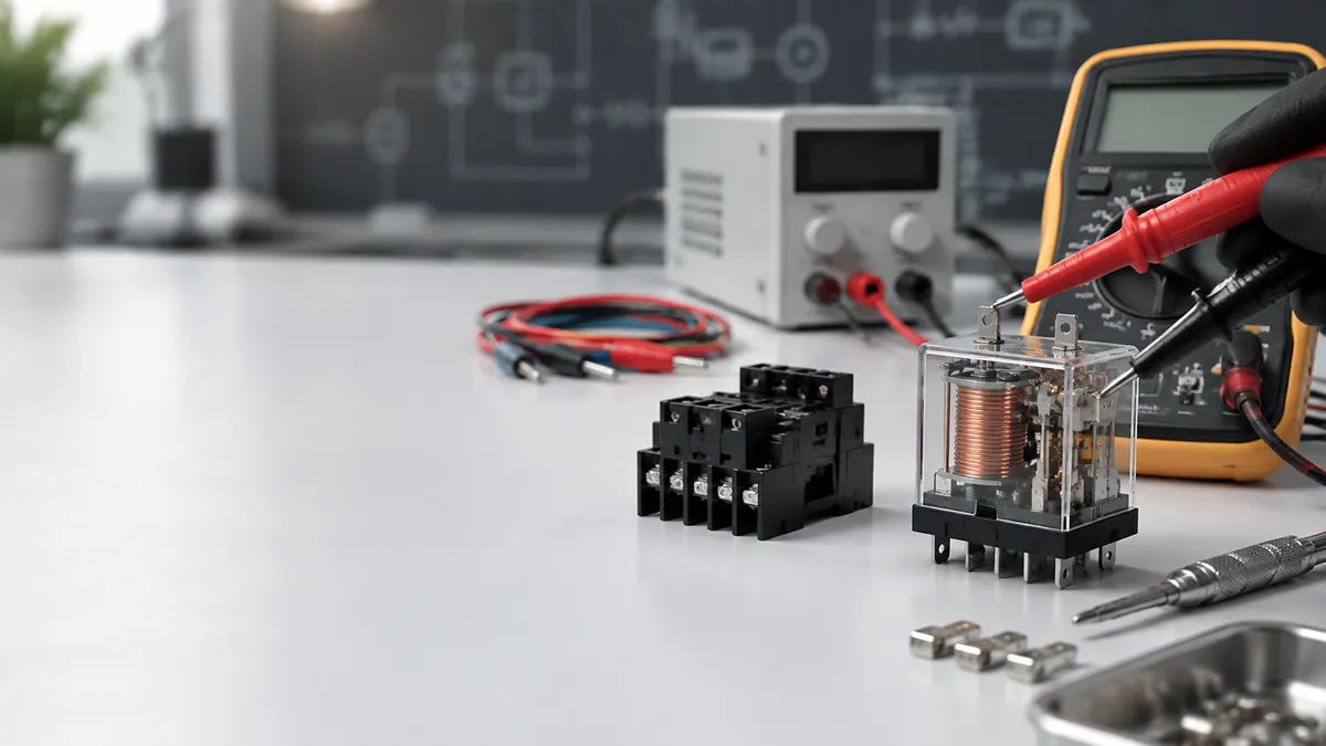
Testing a relay is mainly about confirming three things: whether the coil is working properly, whether the contacts switch as they should, and whether the relay can operate correctly in the actual circuit.
Different tools reveal different levels of fault. A multimeter, for example, is useful for measuring coil resistance, continuity, voltage, and voltage drop, but it is not the only way to check a relay. Depending on the situation, you may also use a visual inspection, a known-good relay, a battery and jumper wires, a Power Probe, or an under-load voltage-drop test.
The table below provides a quick overview of the six methods covered in this guide.
| Method | Tool Required | Best Used For | Main Limitation |
|---|---|---|---|
| Visual inspection | None | Finding obvious physical damage | Cannot detect most internal electrical faults |
| Relay swap test | Identical known-good relay | Quick troubleshooting, especially in vehicles | Does not show what is wrong inside the relay |
| Multimeter test | Digital multimeter | Coil, contact, voltage, and continuity checks | Static tests may not reveal faults under load |
| Battery/jumper test | Correct-voltage source and jumper leads | Checking whether a relay can energize and switch | A click alone does not confirm healthy contacts |
| Power Probe test | Power Probe or similar powered tester | Fast automotive and low-voltage circuit diagnosis | Not suitable for blindly powering unknown circuits |
| Voltage-drop test | Digital multimeter | Finding high-resistance contacts under load | Requires the circuit to be operating |
The important point is that these methods are not simply interchangeable. Each one answers a slightly different diagnostic question.
Identify the Relay Before Testing It
Before connecting a meter, battery, or powered circuit tester, first determine what kind of relay you are dealing with.
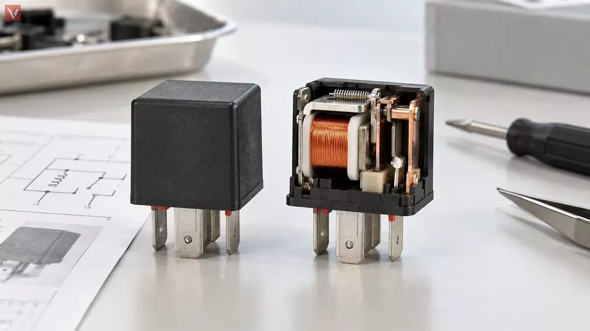
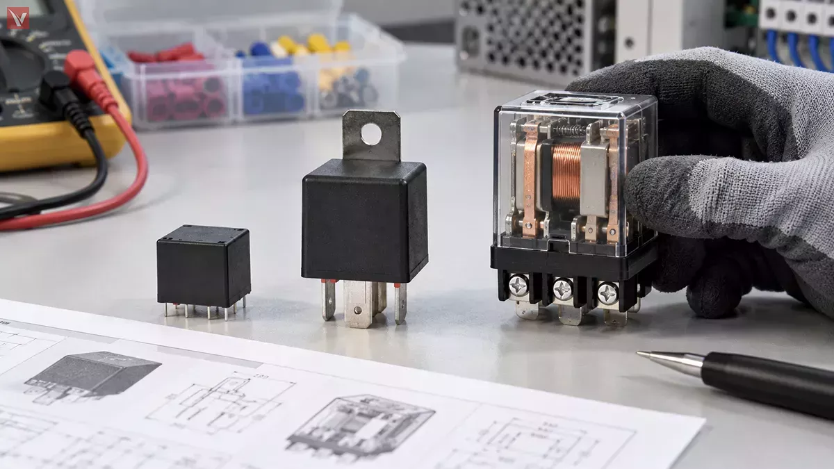
This matters because the familiar 4-pin or 5-pin automotive relay is only one type of relay. PCB relays, power relays, signal relays, latching relays, reed relays, and solid-state relays can have different terminal arrangements and require different testing approaches.
For a conventional electromechanical relay, you normally need to identify two parts of the circuit: the coil and the switching contacts. When voltage is applied to the coil, it creates a magnetic field that moves an internal armature. That movement changes the state of the contacts.
A typical relay may include a common terminal (COM), a normally open terminal (NO), and sometimes a normally closed terminal (NC). On many automotive relays, terminals 85 and 86 are used for the coil, terminal 30 is common, terminal 87 is normally open, and terminal 87a is normally closed.
However, this numbering should never be assumed for every relay.
For PCB relays and many industrial products, the safest approach is to check the schematic printed on the housing or locate the manufacturer's datasheet. The datasheet also tells you something equally important: the relay's rated coil voltage.
A 5 V relay, a 12 V automotive relay, and a 24 V industrial relay may all look similar in principle, but they cannot be energized with the same test voltage. Some relays also contain an internal suppression diode or other protective component, which can make coil polarity important.
In short, identify the relay first and test it according to its actual electrical specifications rather than its appearance alone.
Start With a Visual Inspection or Relay Swap
The easiest relay checks require almost no test equipment. They are useful as a first step because they can sometimes identify the problem before more detailed electrical testing is necessary.
Method 1: Visual Inspection
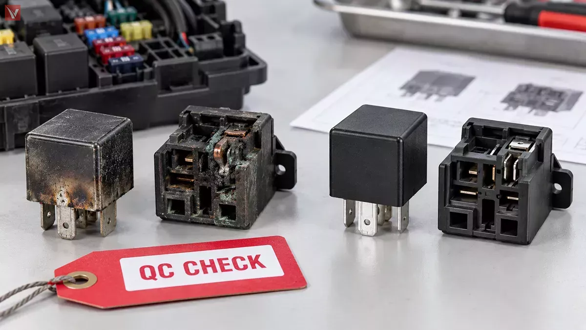
Inspect both the relay and, where applicable, its socket. Look for obvious evidence of heat, discoloration, melted plastic, corrosion, cracked housing, bent terminals, loose connections, or moisture contamination.
The socket deserves particular attention. A relay may be perfectly functional while a loose or overheated socket terminal creates enough resistance to prevent the connected load from operating correctly.
Physical damage can give you a useful clue, but a normal-looking relay should not automatically be considered good. An open coil, worn contact, or intermittent internal connection may leave no visible evidence at all.
That is why visual inspection works best as a preliminary check rather than a final diagnosis.
Method 2: Swap With a Known-Good Relay
In applications where several identical relays are used, particularly automotive fuse and relay boxes, a swap test can provide a fast answer.
The basic idea is simple: replace the suspected relay temporarily with another relay known to work. If the fault moves with the relay or the affected system begins working again, the original relay becomes the likely cause.
The important word here is identical. Two relays that have the same physical size or number of terminals may still have different coil voltages, contact arrangements, internal suppression components, or current ratings.
For that reason, verify the part number and electrical specifications before swapping them.
A swap test is useful when you want a quick answer without a multimeter, but it does not explain why the original relay failed. For that, an electrical test is more useful.
How to Test a Relay With a Multimeter
A digital multimeter is usually the most versatile tool for relay diagnosis because it allows you to examine both the coil and the switching contacts instead of simply checking whether the relay clicks.
Check the Coil Resistance
Disconnect the relay from power and identify the coil terminals. Set the multimeter to resistance mode and measure across the coil.
An open-circuit or OL reading usually indicates that the coil winding is broken. An unusually low resistance may indicate a shorted winding. A stable resistance reading suggests that the winding is electrically continuous, although it does not by itself prove that the complete relay is working correctly.
One common mistake is assuming that every good relay should have the same resistance.
It should not.
Coil resistance varies with relay design, rated coil voltage, and coil power. A resistance value that is normal for one 12 V relay may be completely inappropriate for another type of relay. Generic resistance ranges can be useful as rough references for certain automotive relays, but the manufacturer's specification is the better standard whenever it is available.
For example, if a relay has a 12 V coil and measures 120 Ω, its approximate coil current can be estimated from Ohm's law as:
12 V ÷ 120 Ω = 0.1 A, or 100 mA
This relationship can help you determine whether a measured value is reasonable when you also know the relay's rated coil power or current.
Checking the Switching Contacts
After checking the coil, identify the COM, NO, and NC terminals.
For a typical SPDT relay, the expected contact state changes when the coil is energized:
| Relay State | COM to NC | COM to NO |
|---|---|---|
| Coil not energized | Closed | Open |
| Coil energized | Open | Closed |
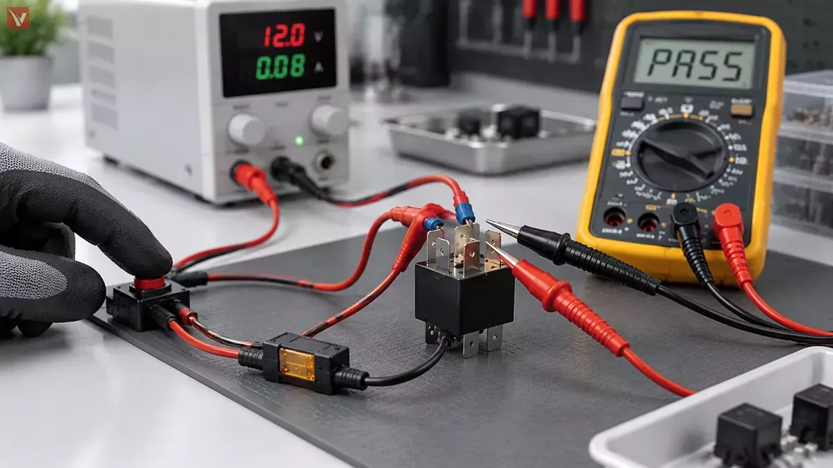
You can verify these states with the continuity or resistance setting of the multimeter.
If the contact state does not change when the coil is energized, the relay may have a mechanical or contact fault.
However, a continuity beep should not be treated as absolute proof that the relay is healthy. A multimeter uses only a very small test current in continuity mode. Contacts that are burned or badly worn may still conduct enough current to trigger the beep but perform poorly when connected to a real load.
This is why multimeter testing is very useful, but a static continuity check is not necessarily the final step.
What If the Relay Tests are Good?
If the coil and contacts behave correctly on the bench but the equipment still does not work, move beyond the relay itself.
The socket may be missing its supply voltage, control signal, or ground. The fuse or wiring may be faulty, a terminal may be loose, or the connected motor, lamp, solenoid, or other load may have failed.
This distinction is essential in relay diagnosis:
A relay test checks the component. A circuit test checks whether the system is actually able to use that component.
How to Test a Relay With a Battery and Jumper Wires
Another common method is to energize an electromechanical relay directly using an appropriate external power source.
This is especially useful for bench-testing low-voltage DC relays.
Method 4: Apply the Rated Voltage to the Coil
After identifying the coil terminals, connect them to a power source that matches the relay's rated coil voltage. For a conventional 12 V automotive relay, for example, an appropriate 12 V supply can be used.
When energized, a working electromechanical relay will normally produce an audible or tactile click as the armature moves.
That click is useful information, but it should not be misunderstood.
A relay can click and still be bad.
The sound confirms that the coil generated a magnetic field and the mechanical mechanism moved. It does not prove that the electrical contacts are clean, low-resistance, or capable of carrying the required current.
A more complete battery test therefore combines coil activation with verification of the switching contacts. You can use a multimeter, an appropriate test light, or a suitable low-voltage test circuit to confirm that the expected contact actually closes when the coil is energized.
Take particular care with the test voltage. Never assume that a relay is designed for 12 V simply because it is an electromechanical relay. PCB relays commonly use lower coil voltages, while industrial relays may use higher DC or AC coil voltages.
Fused jumper leads are also preferable where appropriate, especially when testing automotive circuits, because an accidental short can otherwise allow very high current to flow.
If the relay includes an internal suppression diode, verify the required polarity before applying power.
How to Test a Relay With a Power Probe
A Power Probe or similar powered circuit tester is particularly useful when troubleshooting automotive and other low-voltage DC circuits.
Its purpose overlaps with a multimeter—to determine whether the relay and circuit are functioning correctly—but the way it approaches the problem is different.
A multimeter is primarily used to measure what the circuit is doing. A Power Probe can also be used to actively make part of the circuit do something by supplying power or ground where appropriate.
That difference can make fault isolation much faster.
Method 5: Actively Test the Relay Circuit
Consider an automotive cooling-fan circuit. The fan does not operate, and the relay is one possible cause.
With a multimeter, you may check coil resistance, socket voltage, ground, the ECU control signal, and contact continuity one step at a time.
With a suitable powered circuit tester, a technician can instead identify the appropriate relay-control connection and deliberately provide the required power or ground signal. If the relay activates and the cooling fan begins running, that immediately provides useful information: the relay and at least part of the load-side circuit are capable of operating.
The original problem may therefore be further upstream on the control side.
The result of a Power Probe test should be interpreted in context:
| Test Result | What It May Indicate |
|---|---|
| Relay activates and load operates | Relay and load-side circuit are probably functional |
| Relay clicks but load does not operate | Check contacts, supply path, socket, wiring, and load |
| Relay does not activate | Check coil, terminal identification, power/ground, or relay condition |
| Load operates when manually activated but not normally | Investigate the original control circuit or control signal |
This is why a Power Probe can be especially useful for automotive technicians: it allows the circuit to be actively challenged, rather than simply observed.
Can a Power Probe Replace a Multimeter
Not completely. If you need to know the exact coil resistance, measure small voltage differences, check precise circuit voltage, or diagnose contact resistance, a multimeter is generally the better instrument.
The Power Probe is more valuable when you want to quickly activate a known low-voltage circuit and see how the system responds.
The two tools therefore complement each other.
A useful way to think about them is:
- Multimeter: measure and verify.
- Power Probe: activate and isolate.
There is also an important safety limitation. Never inject power or ground into an unknown terminal simply to see what happens. Modern vehicles and electronic equipment can contain ECU outputs, semiconductor drivers, sensors, and communication circuits that may be damaged by inappropriate external power.
Before using a powered probe, the terminal function, expected voltage, polarity, and circuit design should be understood.
Test the Relay Under Load With a Voltage-Drop Test
Some relay faults only become visible when the relay is carrying real current.
This is one of the reasons a relay can pass several basic tests and still cause problems in actual operation.
Imagine that the coil resistance is normal. The relay clicks. The NO contact passes a continuity test. Everything appears correct.
But when the relay is asked to supply a motor or another relatively high-current load, the device runs slowly, operates intermittently, or does not run at all.
The cause may be excessive resistance at the contacts or connections.
Method 6: Measure Voltage Drop Across the Closed Contacts
A voltage-drop test is performed while the circuit is energized and the relay is carrying its normal load.
Instead of testing whether the two sides of a closed contact are electrically connected, you measure the voltage difference across that connection while current is actually flowing.
A healthy closed contact should produce only a small voltage drop. If the drop becomes excessive, the relay may have burned, oxidized, pitted, or worn contacts. A loose or damaged relay socket can produce similar symptoms.
This test answers a question that continuity testing cannot:
Can the relay carry real operating current without losing excessive voltage?
There is no single voltage-drop value that should automatically be used for every relay. The acceptable value depends on the circuit voltage, load current, relay construction, connections, and manufacturer specifications.
What matters diagnostically is that an unexpected voltage loss across a supposedly closed switching path indicates unwanted resistance somewhere in that path.
This makes voltage-drop testing especially useful when a relay works on the bench but fails intermittently or performs poorly in the actual system.
Which Relay Testing Method Should You Use
The best relay test depends on the question you are trying to answer.
If you simply want to know whether there is visible damage, inspection may be enough to begin. If you have an identical known-good relay, swapping it can quickly identify whether the fault follows the component.
If you need to determine whether a coil is open or whether NO and NC contacts are changing state, a multimeter provides much better information. If you want to see whether an electromechanical relay physically activates, an appropriate power supply or battery can provide a straightforward bench test.
For automotive troubleshooting, a Power Probe can be particularly effective when you need to actively energize a known circuit and separate a control-side problem from a relay or load-side problem.
And when a relay passes basic resistance and continuity checks but still performs badly under real operating conditions, a voltage-drop test becomes much more valuable.
A practical diagnostic sequence can therefore look like this:
| What You Need to Know | Most Useful Test |
|---|---|
| Is there obvious physical damage? | Visual inspection |
| Is the suspected relay causing the problem? | Known-good relay swap |
| Is the coil electrically intact? | Multimeter resistance test |
| Do the contacts change state? | Multimeter continuity test |
| Does the relay physically activate? | Correct-voltage battery/power test |
| Will the circuit respond when actively commanded? | Power Probe test |
| Can the contacts carry the real load properly? | Voltage-drop test |
In many cases, a reliable diagnosis comes from combining two or more methods rather than looking for one universal relay test.
For example, a relay might pass its coil-resistance test and click when powered, yet fail the final voltage-drop test because its contacts have deteriorated. Each method reveals a different layer of information.
Choosing a Replacement Relay
If testing confirms that the relay has failed, avoid choosing a replacement based only on appearance or pin count.
The replacement should match the original relay's coil voltage, contact configuration, current and voltage ratings, pinout, mounting style, and switching requirements. Depending on the application, factors such as internal suppression components, operating temperature, isolation, contact material, and electrical life may also matter.
This is particularly important for PCB and industrial relays, where two physically similar components may have very different electrical characteristics.
When possible, use the original part number or manufacturer datasheet to confirm compatibility before installing the replacement.
Frequently Asked Questions
Can a relay click and still be bad?
Yes. The click only tells you that the electromagnetic mechanism moved. The contacts may still be burned, worn, stuck, or excessively resistive. Checking contact continuity and, where necessary, voltage drop under load provides a more complete diagnosis.
How can you test a relay without a multimeter?
A known-good relay swap is one of the simplest methods. For suitable low-voltage electromechanical relays, you can also apply the correct rated voltage to the coil and check whether the relay activates and switches the circuit. These tests are useful, but they provide less diagnostic detail than a multimeter.
How many ohms should a good relay have?
There is no universal resistance value for all relay coils. The correct resistance depends on the rated coil voltage, coil power, construction, and relay model. The manufacturer's datasheet is the best reference.
Can you test a relay with a Power Probe?
Yes, particularly in automotive and other low-voltage DC systems. A Power Probe can check circuit conditions and actively apply power or ground to appropriate points, making it useful for confirming relay activation and isolating control-side versus load-side faults.
Is a Power Probe better than a multimeter for testing relays?
They serve different purposes. A multimeter is better for precise measurements such as resistance, voltage, continuity, and voltage drop. A Power Probe is useful for quickly activating known low-voltage circuits and observing their response. In professional troubleshooting, the tools are often used together.
Why does a relay work on the bench but not in the circuit?
If a relay passes a bench test but fails in service, the problem may be outside the relay. Possible causes include a weak or missing control signal, insufficient supply voltage, poor ground, damaged wiring, a loose socket, a faulty load, or excessive resistance that only appears under operating current.
Final Thoughts
There is more than one way to test a relay, because not every relay failure looks the same.
A visual inspection or swap test can provide a fast first answer. A multimeter can reveal coil and contact problems. A battery or external supply can confirm mechanical activation. A Power Probe can make fault isolation faster in suitable automotive and low-voltage circuits. And a voltage-drop test can reveal contact problems that only appear when the relay is carrying a real load.
The most important principle is to understand what each test actually proves.
A click does not automatically mean the contacts are healthy. A continuity beep does not guarantee that the relay can carry its rated load. And a relay that works perfectly on the bench may still fail to operate in a system with poor wiring, a damaged socket, or an incorrect control signal.
Identify the relay first, choose the test method according to the fault you are trying to isolate, and compare measured values with the correct datasheet whenever possible.