In modern electronic systems, efficient power management is not optional—it is foundational. Whether you're designing embedded systems, industrial controllers, or battery-powered devices, selecting between a buck converter vs boost converter directly impacts performance, efficiency, thermal behavior, and system reliability. This guide breaks down both topologies from an engineering and application perspective, helping you make informed design decisions.
What Is a Buck Converter and How It Works
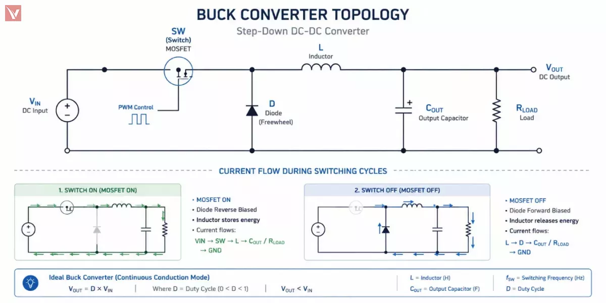
A buck converter is a DC-DC power converter that steps down input voltage to a lower output voltage while maintaining high efficiency. It is widely used in systems where the supply voltage exceeds the required load voltage—for example, stepping down 12V to 5V or 3.3V for logic circuits.
How a Buck Converter Works
The operation of a buck converter is based on high-frequency switching and energy storage elements:
- When the switch (typically a MOSFET) is ON, current flows from the input through the inductor to the load. During this phase, the inductor stores energy in its magnetic field.
- When the switch turns OFF, the inductor resists the sudden drop in current and releases stored energy. The current continues flowing through the diode (or synchronous MOSFET), maintaining output continuity.
- The output capacitor smooths voltage ripple, ensuring a stable DC output.
This rapid switching cycle (often in the hundreds of kHz or MHz range) results in an averaged output voltage lower than the input.
From a design standpoint, the inductor plays a critical role in minimizing current ripple, while switching frequency and duty cycle determine the final output voltage:

Where D is the duty cycle.
How Does a Boost Converter Step Up Circuit Voltage
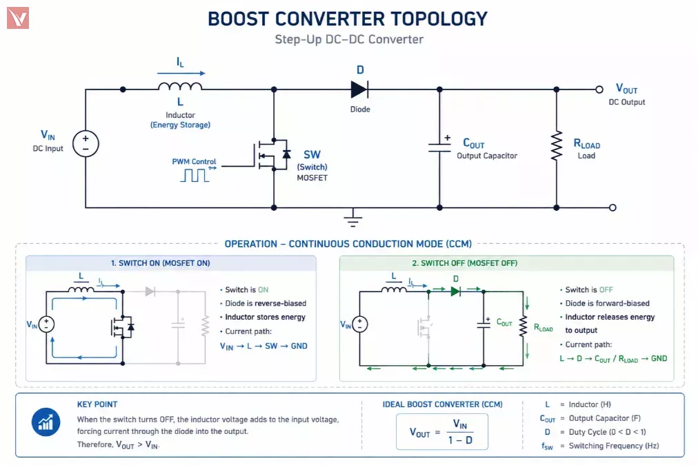
A boost converter performs the opposite function—it increases (steps up) the input voltage to a higher output voltage. This is essential in battery-powered systems where the input voltage may be lower than required by certain components.
How a Boost Converter Works
The boost converter relies on energy accumulation and release through the inductor:
- When the switch is ON, the inductor is connected directly to the input voltage, and current builds up through it, storing energy.
- When the switch turns OFF, the inductor generates a reverse electromotive force (EMF). This voltage adds to the input voltage, effectively boosting the output.
- The diode ensures current flows only toward the output, while the capacitor smooths the resulting higher voltage.
The key mechanism is that the inductor's collapsing magnetic field produces a voltage higher than the input, enabling step-up conversion.
The ideal relationship is:

This means that as the duty cycle increases, the output voltage rises significantly—though practical limits apply due to efficiency losses and component stress.
Buck Converter vs Boost Converter Key Performance Differences
While both converters are essential, their performance characteristics differ significantly depending on application constraints.
Core Comparison
| Parameter | Buck Converter (Step-Down) | Boost Converter (Step-Up) |
|---|---|---|
| Efficiency | Typically higher (90–95%), especially at moderate loads | Lower due to higher switching stress and conduction losses (80–90%) |
| Output Ripple | Lower ripple, easier filtering due to continuous current | Higher ripple, requires careful capacitor and layout design |
| BOM Cost | Lower; fewer stress requirements on components | Higher; requires higher-rated diodes, inductors, and switches |
| PCB Area | More compact for equivalent power levels | Larger due to higher current paths and thermal considerations |
Practical Insight
For most digital systems (MCUs, FPGAs), buck converters are preferred because input rails are often higher than required voltages. Boost converters become critical when dealing with low-voltage sources such as lithium batteries or energy harvesting systems.
Understanding the Combined Buck and Boost Converter Topology
A common point of confusion is the concept of a buck and boost converter. This refers not to choosing one over the other, but to a combined topology capable of both stepping up and stepping down voltage.
What Is a Buck-Boost Converter?
A buck-boost converter can regulate output voltage regardless of whether the input voltage is above or below the target output. This is particularly useful in:
- Battery-powered devices where voltage drops over time
- Automotive systems with fluctuating supply rails
- Portable electronics requiring stable output under varying input conditions
How It Works
The circuit dynamically adjusts switching behavior:
- Acts as a buck converter when

- Acts as a boost converter when

Advanced topologies like 4-switch buck-boost or SEPIC provide smooth transitions without output interruption.
Example
Consider a lithium-ion battery system (3.0V–4.2V) powering a 3.3V rail:
- At full charge (4.2V), the converter operates in buck mode
- As voltage drops below 3.3V, it switches to boost mode
This ensures uninterrupted system performance.
Practical Circuit Design for Security Camera Power Systems
Security camera systems provide a strong real-world example of how both buck and boost converters are used together.
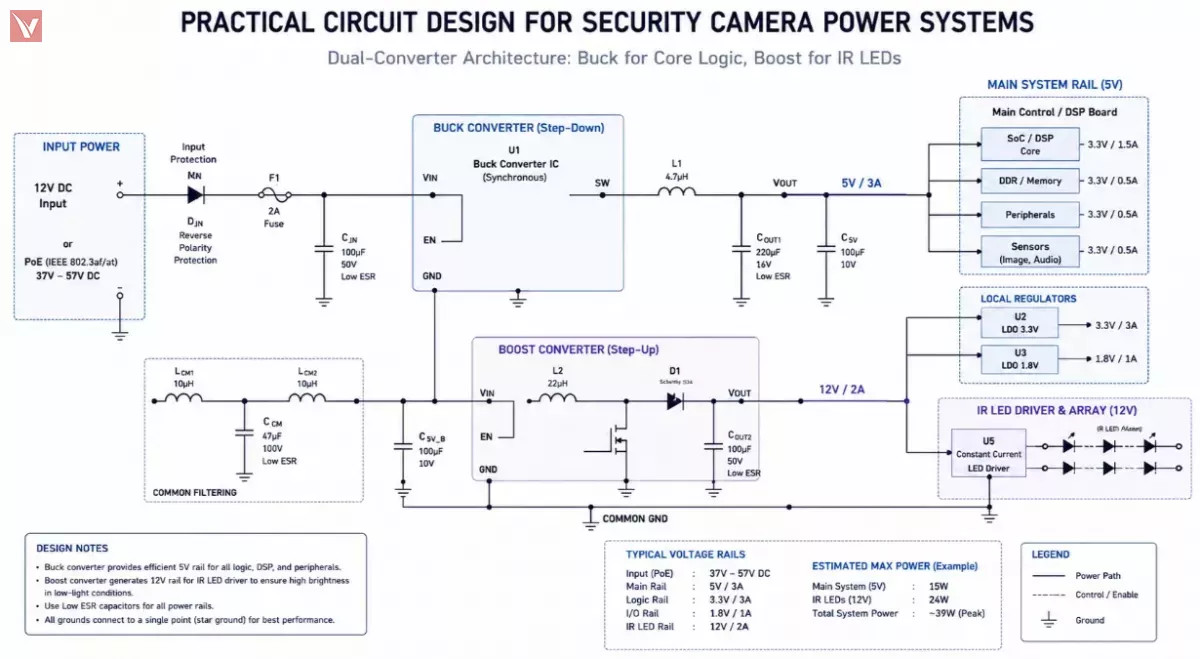
Power Requirements Breakdown
A typical IP camera system includes:
- Main processor (DSP/SoC): Requires stable low-voltage rails (e.g., 1.2V, 3.3V)
- Image sensor module: Sensitive to noise, needs low ripple power
- Infrared (IR) LEDs for night vision: Often require higher voltage than system supply
- Networking modules (PoE or Wi-Fi): Variable input conditions
Converter Strategy
- Buck converters are used to step down PoE input (e.g., 48V → 12V → 3.3V)
- Boost converters power IR LED arrays, raising voltage for sufficient illumination
- Buck-boost converters stabilize voltage for subsystems when input fluctuates
Design Considerations
- Thermal management is critical due to enclosed housing
- Low ripple is essential for image quality
- High efficiency reduces heat and extends product lifespan
This kind of system-level thinking is exactly where selecting the right topology—and component quality—becomes a competitive advantage.
Procuring Reliable Vicor Components Through Global Independent Distributors
In today’s volatile supply chain environment, sourcing reliable DC-DC converters is no longer just a procurement task—it is a design risk factor. Engineers increasingly prioritize high efficiency, low thermal footprint, and power density, especially in compact or mission-critical systems.
Vicor stands out in this domain with its advanced high-density power modules, offering:
- Exceptional efficiency and thermal performance
- Compact modular designs for space-constrained applications
- Scalable architectures for industrial and embedded systems
However, access to such components can be constrained by lead times, allocation policies, or regional supply limitations.
Addressing Supply Chain Pain Points
This is where working with a global independent distributor becomes strategically valuable. Instead of relying solely on franchised channels, companies can gain:
- Access to hard-to-find or end-of-life components
- Flexible sourcing across global inventories
- Faster response to urgent production needs
Why Choose Vigor Components
As a specialized distributor in electronic components, Vigor Components supports engineering and procurement teams by aligning sourcing with real-world design challenges:
- Verified supply of genuine Vicor power management components
- Stable lead time solutions to reduce production uncertainty
- Flexible procurement support, including buffer stock strategies for long lifecycle products
For teams working on power-sensitive applications like industrial cameras, embedded systems, or telecom equipment, this reduces both technical and operational risk.
If you are evaluating DC-DC converter options or facing sourcing constraints, you can submit your BOM directly to Vigorcomp to receive tailored support and competitive quotations.
Optimize Your Power Design with Reliable DC-DC Components
Looking for high-efficiency buck, boost, or buck-boost converters for your next design? Vigorcomp provides genuine Vicor power modules, fast global sourcing, and flexible supply solutions to help you reduce risk and improve performance.
Contact US →