
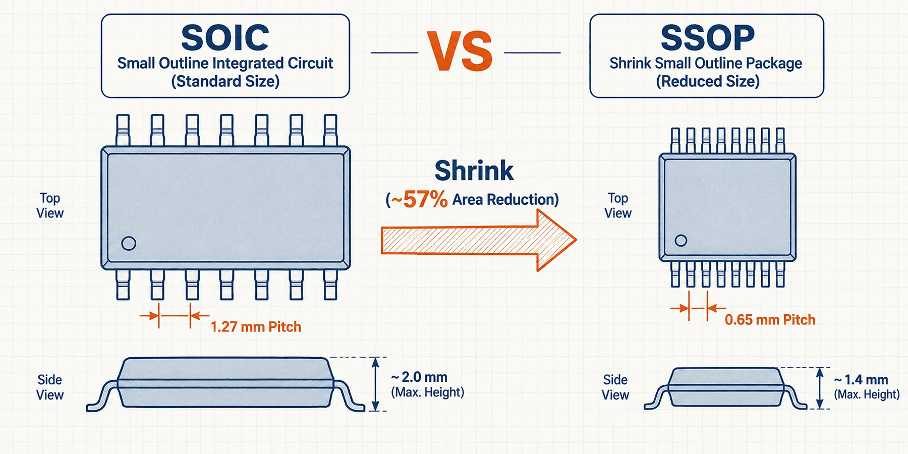
Small Outline Integrated Circuit (SOIC) and Shrink Small Outline Package (SSOP) are dual-row surface-mount IC packages with gull-wing leads, but their PCB footprints are completely incompatible and cannot be swapped on an existing circuit board. The core mechanical difference is miniaturization: standard SOIC packages use a 1.27 mm (50 mil) pin pitch, whereas SSOP packages compress the pin pitch to 0.65 mm (or 0.635 mm on 25-mil variants) and narrow the molded plastic body. On 20-pin and 28-pin components, moving from a wide-body SOIC to an SSOP reduces total board area by roughly 57%, though this space reduction requires tighter PCB trace routing, finer stencil apertures, and strict verification of manufacturer part suffixes during BOM procurement.
SOIC vs SSOP: Quick Comparison Table
Before evaluating specific pin counts or land patterns, hardware designers and buyers can compare the primary mechanical and assembly parameters of the two package families below.
| Feature / Parameter | SOIC (Small Outline Integrated Circuit) | SSOP (Shrink Small Outline Package) |
|---|---|---|
| Full Package Name | Small Outline Integrated Circuit | Shrink Small Outline Package |
| Standard Lead Pitch (e) | 1.27 mm (50 mil) | 0.65 mm (standard EIAJ/JEDEC MO-150) or 0.635 mm (25 mil QSOP/MO-137) |
| Typical Body Width (E1) | 3.90 mm (Narrow, MS-012) or 7.50 mm (Wide, MS-013) | 5.30 mm (209 mil standard) or 3.90 mm (150 mil QSOP) |
| Typical Seated Height (A max) | 1.75 mm (Narrow) to 2.65 mm (Wide) | 2.00 mm (typical max for 20/28-pin SSOP) |
| Common Pin Counts | 8, 14, 16 (Narrow); 16W, 20, 24, 28 (Wide) | 14, 16, 20, 24, 28, 38, 48, 56 |
| PCB Footprint Compatibility | Not interchangeable with SSOP | Not interchangeable with SOIC |
| Manual Soldering & Rework | Easy (wide 1.27 mm spacing, ~0.67 mm inter-pad gap) | Moderate to Challenging (~0.20 mm inter-pad gap at 0.65 mm pitch) |
| Best Suited Applications | Industrial controls, power/analog ICs, prototypes, designs prioritizing easy inspection | Compact 20- to 56-pin MCU, logic, and interface designs requiring ~57% board area savings |
What Does SOIC Mean?
In component datasheets and BOM descriptions, the SOIC meaning is straightforward: the SOIC IC package style full name is Small Outline Integrated Circuit. Developed as the foundational surface-mount successor to the through-hole Dual In-line Package (DIP), a small outline integrated circuit occupies roughly 30% to 50% of the board area and about 30% of the vertical thickness of an equivalent DIP while maintaining a familiar dual-row pin numbering layout. If you are comparing broader surface-mount and through-hole options across a board, see our overview of common types of IC packages.
Structurally, an SOIC consists of a rectangular molded plastic body with metallic gull-wing leads extending from the two longer sides. Standard SOIC packages feature a plain plastic underside designed to sit slightly above the PCB surface (standoff height \(A1\) of \(0.10\text{ mm}\) to \(0.30\text{ mm}\)). Only specialized high-power thermal variants—often designated as HSOP or SOIC PowerPAD—incorporate an exposed metal thermal pad on the bottom of the package.
JEDEC Narrow (MS-012) vs Wide (MS-013) and JEITA Standards
While every standard SOIC shares a 1.27 mm (0.050 in / 50 mil) center-to-center lead pitch ( \(e\)), the molded body width ( \(E1\)) splits into two distinct JEDEC standards depending on the pin count and internal silicon die size:
- JEDEC MS-012 (Narrow Body SOIC): Features a nominal body width ( \(E1\) ) of 3.90 mm (150 mil) and an outer lead-tip-to-lead-tip span ( \(E\) ) of 6.00 mm. This is the standard outline for 8-pin, 14-pin, and most 16-pin logic, op-amp, and memory ICs (such as the TI D or Microchip SN package codes).
- JEDEC MS-013 (Wide Body SOIC): Features a nominal body width ( \(E1\) ) of 7.50 mm (300 mil) and an outer lead span ( \(E\) ) of 10.30 mm. Once an IC reaches 20, 24, or 28 pins (and certain wide 16-pin isolation devices), the standard SOIC transitions to this wide-body outline (such as the TI DW or Microchip SO package codes) (Source: Microchip C04-094).
Engineers and buyers should also watch for regional standard variations. While SOIC typically refers to U.S. JEDEC outlines, Japanese JEITA/EIAJ standards—frequently labeled simply as SOP—use the same \(1.27\text{ mm}\) pitch but often specify an intermediate 5.30 mm body width (such as the TI NS package). Always check the mechanical drawing in the manufacturer datasheet rather than assuming all 1.27 mm outlines share the same pad width.
What Is an SSOP Package?
SSOP stands for Shrink Small Outline Package. As microcontrollers, bus transceivers, and mixed-signal ICs expanded to 20, 28, and 48 pins, the 7.50 mm wide-body SOIC became too long and wide for compact circuit boards. The SSOP package solves this by shrinking both the plastic body width and the lead pitch, allowing higher pin density without switching to four-sided quad flat packages (QFP) or leadless QFN footprints.
Across major semiconductor manufacturers, SSOP mechanical drawings fall into two lead-pitch standards:
- 0.65 mm Pitch SSOP (JEDEC MO-150 / EIAJ Type II): The most common standard for 14-, 16-, 20-, 24-, 28-, and 38-pin SSOP devices. It pairs a 0.65 mm metric lead pitch with a 5.30 mm (209 mil) molded body width and a 7.80 mm outer lead span (Source: Microchip C04-00073).
- 0.635 mm (25 mil) Pitch SSOP / QSOP (JEDEC MO-137): Exactly half the pitch of a standard 50-mil SOIC ( \(0.050\text{ in} \div 2 = 0.025\text{ in}\) ). This variant is commonly used in Quarter-Size Small Outline Packages (QSOP) with a 3.90 mm body width (fitting 16 to 28 pins into the exact length and width of a narrow SOIC) as well as wide 48-pin and 56-pin bus-interface SSOPs (Source: TI SCZA001).
How SSOP Differs from TSSOP
Both SSOP and TSSOP typically use a \(0.65\text{ mm}\) pin pitch, so they are frequently confused during BOM reviews. The primary difference is vertical profile height and body width: a standard SSOP has a maximum seated height ( \(A\)) of 2.00 mm (with a molded body thickness around \(1.65\text{ mm}\) to \(1.85\text{ mm}\)) and a \(5.30\text{ mm}\) body width, whereas a TSSOP (Thin Shrink Small Outline Package) reduces the maximum seated height to 1.00 mm to 1.20 mm and typically narrows the body width to \(4.40\text{ mm}\)(Source: Microchip C04-00073). If your enclosure has strict vertical clearance limits, read our dedicated comparison on the differences between TSSOP and SOIC packages.
Pin-Count Comparison: SOIC 20 vs SSOP 20 and SOIC 28 vs SSOP 28
Comparing 14-pin or 16-pin packages can sometimes obscure why SSOP saves so much board space: a 14-pin narrow SOIC has a \(3.90\text{ mm}\) body width, while a 14-pin EIAJ SSOP has a \(5.30\text{ mm}\) body width—making the SSOP shorter in length but slightly wider across the body.
The real geometric advantage occurs at 20 pins and 28 pins, where standard SOIC packages step up to the 7.50 mm wide body (JEDEC MS-013) with a 10.30 mm outer lead span ( \(E\)). When evaluating PCB layout density, engineers must look at both the nominal molded body dimensions ( \(D \times E1\)) and the total footprint area including the gull-wing leads ( \(D \times E\)).
| Package Variant | Manufacturer Code Examples | Lead Pitch (e) | Nominal Body Length (D) | Nominal Body Width (E1) | Outer Lead Span (E) | Max Seated Height (A) | Total Footprint Area (D × E) |
|---|---|---|---|---|---|---|---|
| SOIC-20 (Wide) | TI: DW / Microchip: SO | 1.27 mm | 12.80 mm | 7.50 mm | 10.30 mm | 2.65 mm | 131.84 mm² (Baseline) |
| SSOP-20 | TI: DB / Microchip: SS | 0.65 mm | 7.20 mm | 5.30 mm | 7.80 mm | 2.00 mm | 56.16 mm² (-57.4% vs SOIC-20) |
| SOIC-28 (Wide) | TI: DW / Microchip: SO | 1.27 mm | 17.90 mm | 7.50 mm | 10.30 mm | 2.65 mm | 184.37 mm² (Baseline) |
| SSOP-28 | TI: DB / Microchip: SS | 0.65 mm | 10.20 mm | 5.30 mm | 7.80 mm | 2.00 mm | 79.56 mm² (-56.8% vs SOIC-28) |
SOIC 20 vs SSOP 20 Dimensions and Footprint Comparison
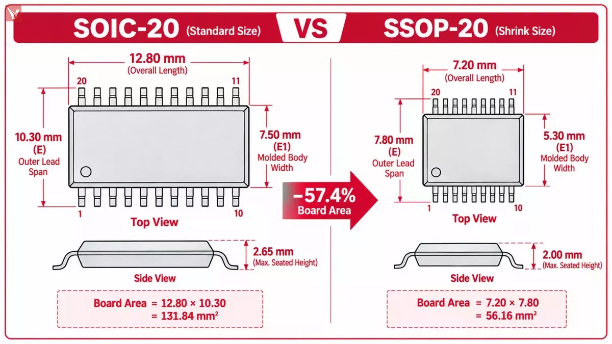
Many 20-pin logic latches, RS-232 line drivers, and USB-to-SPI bridges are manufactured in both wide-body SOIC-20 and SSOP-20 outlines—for example, Texas Instruments' SN74HC373DW (SOIC-20) versus SN74HC373DB (SSOP-20) (Source: TI SN74HC373) and GD75232DW versus GD75232DB (Source: TI GD75232).
- SOIC-20 (TI DW / Microchip SO): Uses a \(1.27\text{ mm}\) lead pitch, a nominal body length ( \(D\) ) of 12.80 mm, and a wide body width ( \(E1\) ) of 7.50 mm ( \(96.00\text{ mm}^2\) body area). Including the gull-wing leads, the outer lead span () reaches 10.30 mm, resulting in a total component footprint area of 131.84 mm² and a maximum height of 2.65 mm (Source: Microchip C04-094).
- SSOP-20 (TI DB / Microchip SS): Compresses the lead pitch to \(0.65\text{ mm}\) , reducing the nominal body length ( \(D\) ) to 7.20 mm and the body width ( \(E1 \) ) to 5.30 mm ( \(38.16\text{ mm}^2\) body area) (Source: TI SN74HC373). With a 7.80 mm outer lead span ( \(E\) ), the total footprint area drops to 56.16 mm² with a 2.00 mm maximum seated height (Source: TI GD75232).
Engineering Takeaway (soic 20 vs ssop 20): Selecting SSOP-20 over SOIC-20 reduces the molded plastic body area by 60.2% and cuts the total lead-to-lead PCB area by 57.4% (saving \(75.68\text{ mm}^2\) per device), while shaving \(0.65\text{ mm}\) off the vertical height.
SOIC 28 vs SSOP 28 Dimensions and Footprint Comparison
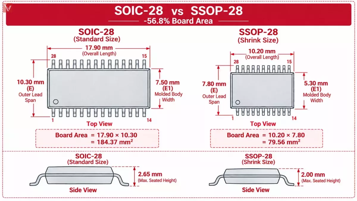
In 8-bit and 16-bit microcontrollers (such as the PIC24HJ32GP202), 16-bit I/O expanders (MCP23017), and multichannel RS-232 transceivers (MAX3243E), 28 pins is one of the most heavily used package counts in industrial hardware.
- SOIC-28 (TI DW / Microchip SO): At a \(1.27\text{ mm}\) pitch across 14 pins per side, the nominal body length ( \(D\) ) stretches to 17.90 mm with a 7.50 mm body width ( \(134.25\text{ mm}^2\) body area) (Source: TI MAX3243E). Combined with the 10.30 mm outer lead span, a single SOIC-28 package consumes 184.37 mm² of board space.
- SSOP-28 (TI DB / Microchip SS): At a \(0.65\text{ mm}\) pitch, the nominal body length ( \(D\) ) drops by \(7.70\text{ mm}\) down to 10.20 mm, paired with a 5.30 mm body width ( \(54.06\text{ mm}^2\) body area) (Source: TI MAX3243E). With its 7.80 mm outer lead span, the total footprint area is 79.56 mm² (Source: Microchip C04-00073).
Engineering Takeaway (soic 28 vs ssop 28): Switching from SOIC-28 to SSOP-28 cuts the molded body area by 59.7% and reduces total lead-to-lead footprint area by 56.8%, freeing up \(104.81\text{ mm}^2\) of PCB real estate per IC (Source: Microchip PIC24HJ32GP202).
Engineering Trade-Offs: PCB Assembly, Thermal Performance, and Electrical Parasitics
Saving nearly 60% of board space does not mean SSOP is automatically superior for every project. Layout engineers and manufacturing teams must balance footprint reduction against assembly tolerances and thermal dissipation.
SMT Stencil Design, Solder Bridging, and Manual Rework
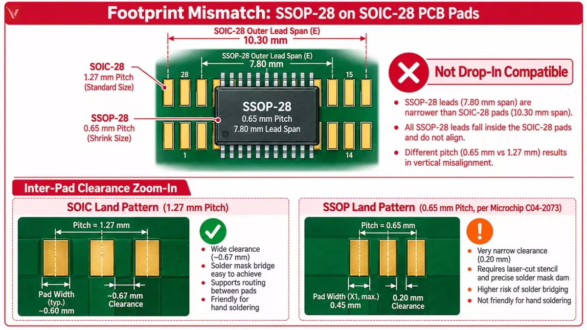
The primary manufacturing constraint of SSOP is inter-pad clearance. According to Microchip's recommended land pattern for a 28-lead SSOP, the copper pads are spaced on a 0.65 mm center-to-center pitch with a maximum recommended pad width ( \(X1\)) of 0.45 mm and pad length ( \(Y1\)) of 1.85 mm (Source: Microchip C04-2073). Subtracting the \(0.45\text{ mm}\) pad width from the \(0.65\text{ mm}\) pitch leaves only 0.20 mm (approx. 7.9 mil) of bare laminate clearance between adjacent copper pads.
- Solder Mask & Stencil Control: A \(0.20\text{ mm}\) gap sits right at the limit for standard green LPI solder mask dams (which typically require at least \(0.075\text{ mm}\) to \(0.10\text{ mm}\) web width to adhere reliably). Without crisp solder mask dams and laser-cut stencil apertures (usually 4 mil or 5 mil foil thickness), excess solder paste can easily bridge adjacent SSOP leads during reflow.
- Inspection & Prototyping: Standard SOIC packages ( \(1.27\text{ mm}\) pitch with \(\sim 0.60\text{ mm}\) pad width) leave roughly 0.67 mm of space between pads—more than triple the clearance of SSOP. This wide gap allows standard 4-mil or 5-mil PCB traces to route between pins, simplifies visual inspection, and allows technicians to hand-solder or probe pins with standard bench tools without shorting adjacent leads.
Thermal Impedance (
\(R_{\theta JA}\)) and Lead Inductance
Package dimensions also directly influence thermal and high-speed electrical behavior:
- Thermal Dissipation ( \(R_{\theta JA}\) ): Because neither standard SOIC nor standard SSOP includes an exposed bottom thermal pad, heat generated by the silicon die conducts primarily through the internal metal leadframe into the PCB copper pads and radiates from the plastic package surface. Because SOIC-20 and SOIC-28 have roughly 2.5 times the plastic surface area and heavier copper leads than SSOP-20/28, the SOIC version generally provides a lower junction-to-ambient thermal impedance ( \(R_{\theta JA}\) ). When operating transceivers or power-management ICs near their maximum current limits at high ambient temperatures, always compare the package-specific \(R_{\theta JA}\) values in the datasheet thermal table.
- Lead Inductance & Ground Bounce: Conversely, the large physical loop of a 7.50 mm wide-body SOIC leadframe introduces higher parasitic self-inductance and capacitance per pin. Because SSOP leads are substantially shorter and closer together, SSOP packages reduce lead inductance and capacitance, which minimizes simultaneous switching noise (ground bounce) in high-speed bus-interface logic (Source: TI SCZA001).
Can You Replace SOIC with SSOP on a PCB or BOM?
During component shortages, buyers frequently find that an IC's SOIC variant is on backorder while the SSOP variant of the exact same base part number is in stock (or vice versa). Before approving an alternative package suffix on a BOM, evaluate three engineering rules:
- No Direct Bare-Board Substitution: Because the pin pitch ( \(\) vs \(\) ) and outer lead span ( \(\) vs \(\) on 20/28-pin parts) differ completely, an SSOP cannot be soldered onto an SOIC PCB land pattern. If boards are already fabricated, you must either source the exact matching package suffix or use an SOIC-to-SSOP PCB interposer/adapter board (practical only for low-volume prototypes where added trace inductance is acceptable).
- Watch Out for Hidden Pin-Count Shifts: Never assume that the SOIC and SSOP versions of the same base part number always have the same number of pins. In certain 8-bit microcontrollers—such as Microchip's PIC16C712/716 and PIC16F716 families—the PDIP and wide SOIC (-I/SO) versions are 18-pin packages, whereas the SSOP version (-I/SS) is a 20-pin package with extra VDD/VSS or no-connect (NC) pins, shifting the pin numbering across the schematic.
- Dual-Footprint PCB Design for Supply Resilience: If you are laying out a new non-critical industrial board and want flexibility against future stockouts, you can place an SSOP land pattern nested inside (or wired in parallel beside) a wide-body SOIC-20/28 footprint. This allows purchasing teams to buy whichever package suffix is available without re-spinning the PCB.
Manufacturer Part Number Package Suffix Reference
To prevent ordering mistakes during BOM scrubbing, verify the orderable package suffix at the end of the part number against the table below:
| Manufacturer | SOIC Narrow (3.90 mm) Suffix | SOIC Wide (7.50 mm, 20/28-Pin) Suffix | SSOP (0.65 mm Pitch, 20/28-Pin) Suffix | Verified Part Number Example (SOIC vs SSOP) |
|---|---|---|---|---|
| Texas Instruments (TI) | D | DW | DB (or DBQ for 0.635 mm QSOP) | SN74HC373DW (SOIC-20) vs SN74HC373DB (SSOP-20) |
| Microchip Technology | SN / SL | SO | SS | MCP23017-E/SO (SOIC-28) vs MCP23017-E/SS (SSOP-28) |
| NXP Semiconductors | D / SO | D / SO (Wide) | DB / SSOP | Verify exact SOT package code in datasheet (e.g., SOT163 vs SOT339) |
When cross-checking BOM availability across multiple package suffixes (such as TI DW vs DB or Microchip /SO vs /SS), always match the complete manufacturer ordering code—including tape-and-reel (R or T) vs tube packaging suffixes—against your assembly house's feeder requirements. If your primary SOIC or SSOP part is facing extended lead times, you can submit your BOM to the Vigorcomp sourcing team to check verified stock across matching package codes or temperature grades.
Frequently Asked Questions
What is the full name of the SOIC IC package style?
The full name of the SOIC IC package style is Small Outline Integrated Circuit. It is a surface-mount package family characterized by a rectangular molded plastic body with gull-wing leads extending from the two longer sides on a standard \(1.27\text{ mm}\)( \(50\text{ mil}\)) center-to-center pitch.
Are SOIC-20 and SSOP-20 pin-for-pin and footprint compatible?
Most 20-pin ICs (such as the SN74HC373 octal latch or GD75232 driver) keep the exact same logical pin numbering order between SOIC-20 and SSOP-20, meaning Pin 1 through Pin 20 carry the same signals. However, they are not footprint compatible: SOIC-20 has a \(1.27\text{ mm}\) pitch and a \(10.30\text{ mm}\) outer lead span, while SSOP-20 has a \(0.65\text{ mm}\) pitch and a \(7.80\text{ mm}\) outer lead span (Source: TI GD75232). Additionally, always verify the datasheet pinout diagram, as a few 18-pin SOIC microcontrollers expand to 20 pins when packaged in SSOP.
What is the difference between SSOP and QSOP?
Standard SSOP (following JEDEC MO-150 / EIAJ Type II) uses a metric 0.65 mm lead pitch and a 5.30 mm (209 mil) nominal body width (Source: Microchip C04-00073). QSOP (Quarter-Size Small Outline Package, following JEDEC MO-137)—which some manufacturers list as a 25-mil SSOP—uses an imperial 0.635 mm (0.025 in) lead pitch and a narrower 3.90 mm (150 mil) body width, fitting twice as many pins into the same body width as a standard narrow SOIC (Source: TI SCZA001).
Is SOP the same as SOIC?
In general component sourcing, SOP (Small Outline Package) and SOIC are often used interchangeably because both feature gull-wing leads with a \(1.27\text{ mm}\) pitch. In strict mechanical specifications, however, SOIC usually denotes U.S. JEDEC outlines ( \(3.90\text{ mm}\) narrow MS-012 or \(7.50\text{ mm}\) wide MS-013), whereas SOP frequently denotes Japanese JEITA/EIAJ outlines with a \(5.30\text{ mm}\) body width (such as the TI NS package). A \(5.30\text{ mm}\) SOP will not fit properly on a \(3.90\text{ mm}\) narrow SOIC PCB footprint, so always verify the datasheet mechanical drawing.
Conclusion
Choosing between SOIC and SSOP comes down to pin count, available PCB area, and assembly process margins:
- Select SOIC when working with 8- to 16-pin narrow-body ICs, when PCB board space is generous, when manual soldering, probing, or field rework is required, or when slightly higher power dissipation benefits from a larger leadframe thermal mass.
- Select SSOP when designing with 20-pin, 28-pin, or higher-pin-count ICs where a 7.50 mm wide-body SOIC consumes too much board area, when automated SMT pick-and-place and laser-cut stencils are standard, and when a ~2.00 mm package height fits your mechanical enclosure.
Need help verifying package suffixes or sourcing hard-to-find SOIC and SSOP components for an upcoming production run? Browse Vigorcomp's integrated circuit catalog or send your BOM list to our procurement team to check verified stock and lead times across exact manufacturer package codes.