DC converters sit at the heart of modern electronic systems because few loads operate efficiently from an unconditioned input rail. In practice, engineers use them to step voltage up or down, stabilize supply rails, improve efficiency, manage thermal loss, and in some cases provide galvanic isolation for safety and system robustness.
For buyers and design teams alike, understanding the major types of DC converters is not only a matter of circuit theory. It is also a sourcing decision that affects BOM risk, second-source flexibility, thermal design, certification effort, and long-term field reliability.
Linear vs Switching Regulators
The first engineering decision is often whether a rail should use a linear regulator or a switching regulator. Linear regulators are simple and quiet, but their theoretical efficiency is fundamentally constrained by the ratio of output voltage to input voltage, while switching regulators are more complex yet typically far more efficient and flexible in practical power conversion tasks.
A linear stage is still appropriate when noise is critical, current is modest, and the voltage drop is small. A switching stage is usually preferred when heat dissipation, battery life, or substantial step-up or step-down conversion matters, especially in distributed power systems such as 48 V to 12 V or 24 V to 5 V rails.
| Attribute | Linear Regulator | Switching Regulator |
|---|---|---|
| Efficiency trend | Limited by voltage drop, often approximated by Vout/VinVout/Vin in simple cases | Can achieve much higher conversion efficiency through switched energy transfer |
| Noise | Lower output noise in many implementations | Higher switching noise, requires layout and filtering care |
| Complexity | Simpler architecture | Higher component and control complexity |
| Best fit | Low-noise, low-drop, lower-power rails | Broad input/output conversion, better thermal performance, higher power density |
3 Core Fundamental Topologies: Buck, Boost, and Buck-Boost
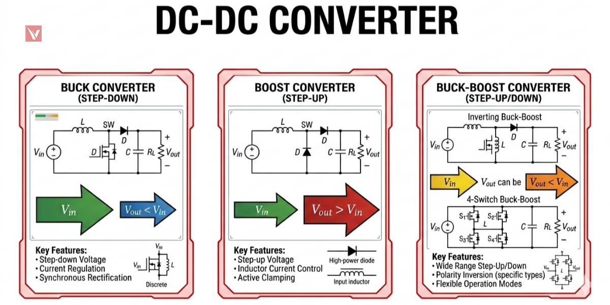
Most engineers begin with three foundational non-isolated topologies: buck, boost, and buck-boost.
The buck converter is the workhorse of board-level power design because it efficiently converts a higher DC rail to a lower rail of the same polarity.
The boost converter raises voltage above the input, while the classic buck-boost extends flexibility but introduces polarity inversion, which limits its usefulness in some mainstream logic-power applications.
| Topology | Main function | Output polarity | Typical use |
|---|---|---|---|
| Buck | Step-down | Same as input | POL rails, embedded systems, telecom boards |
| Boost | Step-up | Same as input | LED drivers, battery-powered systems, bias rails |
| Buck-Boost | Step-up or step-down by magnitude | Opposite to input in classic form | Mixed-voltage designs, negative rails |
For a practical comparison of buck and boost topologies, evaluate voltage direction, efficiency, and application constraints.
Minimizing Output Ripple: Ćuk, SEPIC, and Zeta Designs
Extended non-isolated topologies such as Ćuk, SEPIC, and Zeta are valued because they address practical concerns that standard buck, boost, or inverting buck-boost structures do not fully solve, especially low ripple performance and non-inverted output options in wide-range designs.
The Ćuk converter is known for continuous current characteristics that can help reduce ripple, but it commonly produces inverted output.
SEPIC and Zeta are often discussed when designers need step-up/step-down flexibility without output polarity reversal, though that benefit usually comes at the cost of more components, more complex compensation, and higher design sensitivity.
| Topology | Why engineers choose it | Main trade-off |
|---|---|---|
| Ćuk | Low input/output current ripple, good filtering behavior | Inverted output, added component stress |
| SEPIC | Non-inverted output with wide input range | Lower efficiency than simpler topologies in many designs |
| Zeta | Non-inverted buck-boost-like behavior, useful in some constant-current or tightly managed output cases | More components and control complexity |
Ensuring High-Voltage Safety through Galvanic Isolation
Galvanic isolation is not merely a feature; in many systems it is a safety and compliance requirement. Transformer-based isolated converters break the direct electrical path between input and output, which helps protect users, downstream electronics, and communication interfaces in high-voltage, medical, industrial, and offline power environments. For a practical example of converting 120V mains power to a low-voltage DC supply, see our guide on how to convert 120V to 12V.
TI’s application material explicitly notes isolation as a major advantage in topologies such as flyback, half-bridge, and full-bridge, especially for offline designs. In engineering terms, isolation enables safer fault containment, more flexible grounding strategies, and easier management of noise between domains with different common-mode conditions.
In practical design selection, the decision to isolate should be made early because it affects transformer design, creepage and clearance, EMI strategy, certification path, and sourcing lead times. Isolation adds cost and complexity, but in many regulated or high-energy environments it is the correct design choice rather than an optional enhancement.
Isolated Circuits
Among isolated topologies, four names recur in design reviews: flyback, forward, push-pull, and full-bridge. Each serves a different power range, efficiency target, and input-voltage profile, and choosing well depends on whether the priority is low cost, multiple outputs, transformer utilization, or high-power throughput.
Flyback is often the most accessible isolated topology because it supports one or more outputs and can handle outputs greater or less than the input while keeping cost and component count relatively manageable.
Push-pull is especially attractive in lower input-voltage systems, while full-bridge is commonly used when designers need the highest output power among mainstream isolated PWM topologies because it uses the full input voltage across the transformer primary.
| Topology | Typical strength | Main limitation | Best-fit profile |
|---|---|---|---|
| Flyback | Versatile, supports multiple outputs, relatively economical | Higher ripple/stress at higher power, regulation trade-offs on auxiliary rails | Low to medium power, multiple-output supplies |
| Forward | Better energy-transfer behavior than flyback in many medium-power cases | More components than flyback | Medium-power regulated supplies |
| Push-Pull | Efficient in low-input-voltage systems such as 12 V or 24 V buses | Device matching and voltage stress require care | Battery-powered industrial and vehicular systems |
| Full-Bridge | Highest power capability among listed topologies, strong input-voltage utilization | Higher circuit complexity and gate-drive demands | High-power industrial and telecom conversion |
Bidirectional and Multiphase Interleaved Power
Modern power architectures are expanding beyond one-way conversion. Bidirectional DC-DC converters are increasingly important in EV platforms and energy systems because power must flow in both directions during charging, battery balancing, and regenerative operation, and current industry reviews now treat bidirectional architectures as a distinct and fast-developing topology family. If you are evaluating suppliers for these applications, see our guide to the top global bidirectional DC-DC converter suppliers.
At the board level, multiphase interleaved conversion has become central to high-current digital power. Infineon positions multiphase controllers and power stages for AI servers, storage, routers, switches, telecom base stations, and other data-intensive systems where high current, transient response, and efficiency density are critical.
This section matters because it connects converter theory to visible market demand. Bidirectional power is tied to electrified mobility and energy storage, while multiphase interleaving reflects the needs of CPUs, GPUs, ASICs, and FPGAs that require very high current at low voltage with fast transient behavior.
PWM and PFM Control Strategies
Topology is only part of converter performance; control strategy also shapes efficiency. TI explains PWM as the regulation method in which output voltage is controlled by adjusting the switch on-time, or duty cycle, making PWM the dominant control framework in many classical switching regulators. (Source: Texas Instrument)
In practical products, PWM is often favored at medium to heavy load because it provides predictable switching behavior and easier filtering. PFM, by contrast, is commonly used or blended in light-load conditions to reduce switching loss and improve standby efficiency, although the trade-off may include less uniform ripple behavior and more complex EMI characterization in some implementations.
Critical Performance Metrics for Component Level Selection
Selecting a converter or controller requires more than checking nominal voltage. TI’s guidance highlights duty cycle, inductor ripple current, capacitor ESR, capacitor ESL, grounding quality, and operating mode continuity as parameters that directly affect ripple, loop stability, EMI behavior, and achievable load current.
Several metrics deserve consistent attention during component-level evaluation:
-
Duty cycle range, because it sets practical headroom across the intended input window.
-
Quiescent current, especially in battery-powered or always-on designs where light-load efficiency matters.
-
Output ripple and ripple current tolerance, which are strongly influenced by capacitor ESR and layout quality.
-
Thermal dissipation, efficiency at real operating points, and switching frequency, which together determine magnetics size and heat-sink burden.
For a clearer overview of operating principles and practical selection factors, see our guide to DC converters.
Real-World Deployments across Automotive, Medical, and Telecom
Application context determines topology selection more than textbook elegance. In automotive systems, DC-DC converters support ECUs, safety electronics, ADAS, and powertrain-related functions, while the growth of e-mobility increases demand for both conventional switching converters and more advanced bidirectional architectures.
In medical and industrial environments, isolation becomes especially important because fault separation and grounded-domain management are central design constraints rather than secondary preferences. In telecom and enterprise computing, the main pressure points are power density, efficiency, and fast transient response, which is why multiphase and high-current low-voltage conversion have become so prominent.
| Sector | Common priority | Likely converter direction |
|---|---|---|
| Automotive | Wide input range, ruggedness, efficiency, bidirectional energy flow | Buck, boost, isolated DC-DC, bidirectional |
| Medical | Safety and isolation | Isolated flyback, forward, bridge-based designs |
| Telecom / Data center | Power density, transient response, high current | Multiphase interleaved buck, isolated bus conversion |
| Industrial | Reliability, EMI control, safety separation | Isolated and non-isolated mixed architectures |
Why Engineers and Buyers Choose Vigorcomp
-
Broad Line-Card Coverage: Vigorcomp’s global reach supports the multi-brand sourcing required when converter BOMs include constrained semiconductors or specific passive components.
-
Alternative Sourcing Support: When a primary part shows extended lead times or lifecycle risk, Vigorcomp can help teams identify replacement parts or equivalent options to keep production on schedule.
-
Supply Chain Responsiveness: Vigorcomp provides the agility needed for urgent prototyping, maintenance demand, or production recovery during market volatility.
-
Global Fulfillment Perspective: By widening sourcing and logistics options across regions, Vigorcomp reduces exposure to local disruptions and improves delivery predictability.
-
Consistency and Quality Focus: Vigorcomp guarantees authenticity and provides traceability processes to help ensure that components used in critical DC converter designs meet the reliability expectations of automotive, medical, and industrial applications.
In real projects, topology selection and sourcing strategy should develop together. After choosing the right DC converter topology for efficiency, ripple, isolation, and control performance, engineers and procurement teams can turn to Vigorcomp to turn their engineering choices into a stable, production-ready bill of materials.
Contact US →