
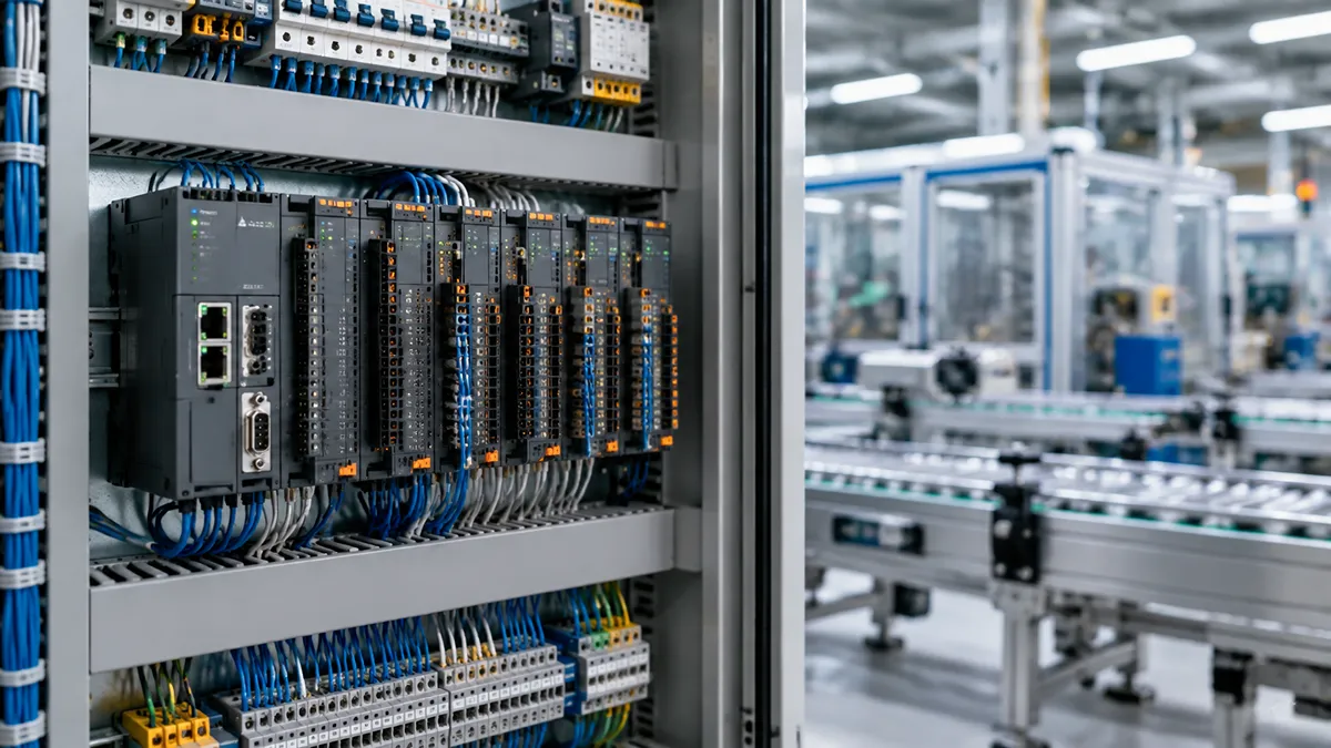
Programmable logic controllers (PLCs) are essential to modern industrial automation. From conveyor belts and packaging machines to water treatment facilities, these devices help industrial equipment operate automatically, consistently, and reliably.
But what exactly is a PLC, and how does it control machines? This guide explains PLC fundamentals, working principles, components, programming, and industrial applications. It also covers practical considerations for selecting a controller and the supporting components needed to build a PLC-based control system.
PLC systems rely on a wide range of electronic components, including processors, memory devices, power management ICs, communication components, and signal isolation devices. Understanding PLC fundamentals also helps engineers better evaluate the electronic components used in industrial control applications.
What Is a Programmable Logic Controller (PLC)?
A programmable logic controller (PLC) is a rugged industrial computer designed to automate machines and processes. It receives signals from input devices, processes them according to a stored program, and controls output devices such as motors, valves, and relays.
Unlike general-purpose computers, PLCs are designed for industrial environments where electrical noise, vibration, temperature variations, and continuous operation can present challenges. Their programmable control logic allows machines to perform repetitive tasks without requiring operators to manage every action manually.
For example, in an automated packaging line, a PLC can detect when a product reaches a particular position, stop a conveyor, activate a packaging mechanism, and restart production once the operation is complete.
What Does PLC Stand For?
PLC stands for Programmable Logic Controller. Each part of the name describes its function:
- Programmable: Its control instructions can be created or modified using software.
- Logic: It makes decisions based on programmed conditions, timing, and input signals.
- Controller: It coordinates and controls industrial equipment.
Before PLCs became widely adopted, many industrial control systems depended on hardwired relays, timers, and switches. PLCs simplified these systems by allowing much of the control logic to be implemented and modified through programming rather than extensive rewiring.
PLC Meaning in Electrical Engineering
In electrical engineering, PLC refers to an electronic controller that monitors electrical input signals and generates outputs to operate equipment.
A typical PLC system connects sensors, push buttons, and switches to input terminals, while output terminals interface with devices such as contactors, indicator lights, and motor drives.
Many industrial PLCs use 24V DC digital signals, although supported voltages depend on the controller and I/O modules. Analog signals, such as 0–10V or 4–20mA, are also commonly used to measure variables including pressure, temperature, and flow.
This ability to interpret different electrical signals makes PLCs valuable in industrial control panels and automated machinery.
How Does a PLC Work?
- Read Input Signals
- Execute User Program
- Update Output Devices
- Repeat Cycle
A PLC operates by continuously monitoring inputs, executing programmed instructions, and updating outputs. This process enables it to respond to changing conditions in industrial equipment.
For example, when a proximity sensor detects a metal object, the PLC can process that signal and activate a pneumatic cylinder to move the object.
The PLC Scan Cycle Explained
Most conventional PLCs use a repeated operating process known as the scan cycle, which generally consists of three stages.
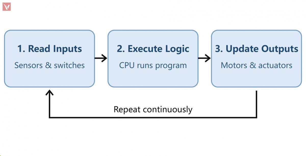
Simplified PLC scan cycle. Actual execution and I/O update behavior vary by controller architecture and task configuration.
During the input stage, the PLC reads signals from connected devices, such as switches, sensors, and transmitters. The CPU then executes the programmed logic, evaluating conditions, timers, counters, and other instructions. Finally, the controller updates its outputs to operate connected machinery.
This cycle repeats continuously, often within milliseconds, depending on program complexity, hardware performance, and controller configuration. Some modern PLCs also use periodic tasks, interrupts, or distributed I/O updates rather than relying solely on one simple scan sequence.
For further background on PLC operation and its role in industrial control systems, see inductiveautomation.com.
Example: Controlling an Industrial Conveyor Belt
Consider a conveyor system that transports products to a packaging station.
A photoelectric sensor detects a product approaching the workstation and sends a signal to the PLC. The PLC checks the programmed conditions and issues a command to stop the conveyor through an appropriate motor controller. Once the packaging mechanism completes its operation, a confirmation signal allows the PLC to restart the conveyor.
The same controller may monitor emergency-stop status, detect equipment faults, and communicate operating information to an HMI. Safety-related stopping functions, however, must be implemented using an appropriate safety-rated architecture rather than relying solely on standard PLC logic.
This example demonstrates how a PLC coordinates multiple electrical and mechanical components through programmable control.
Main Components of a PLC System
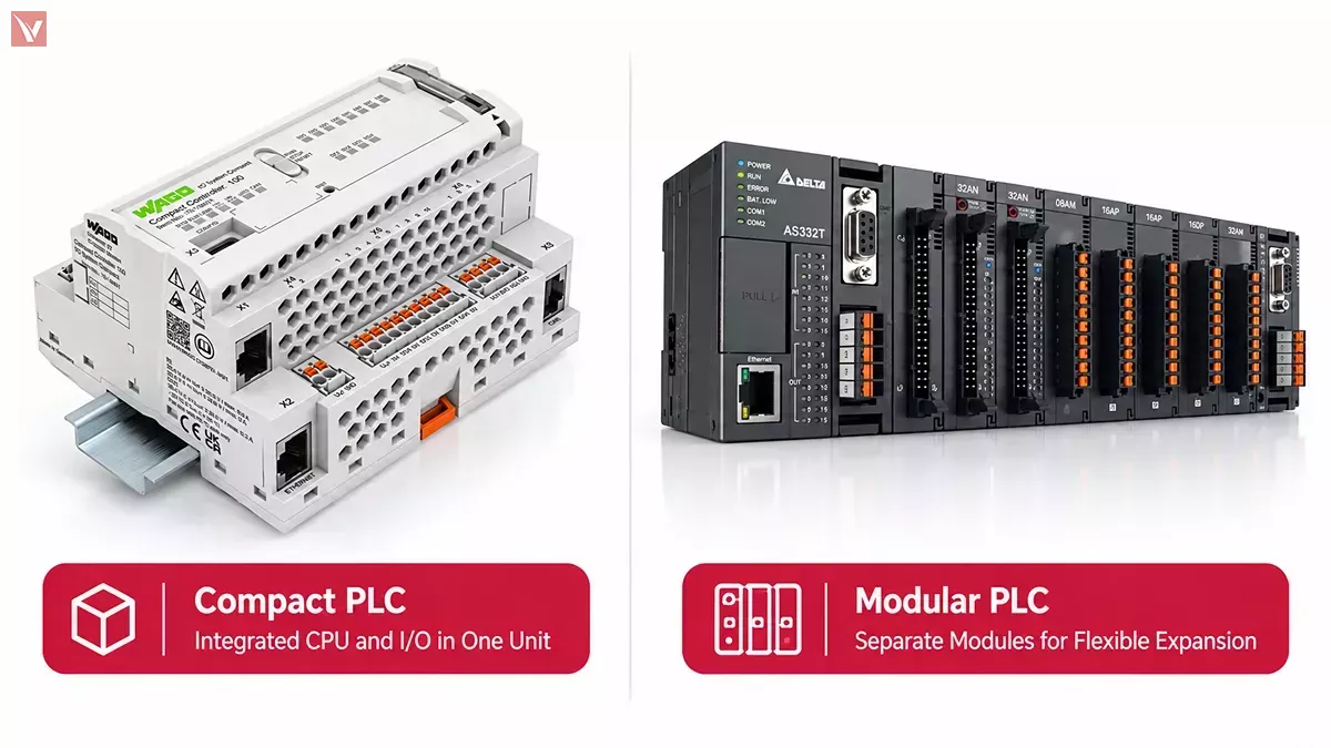
A PLC combines processing hardware, memory, power circuitry, and input/output interfaces. These elements may be housed in a single compact device or assembled as separate modules.
CPU, Memory, and Power Supply
- The central processing unit (CPU) executes the control program and manages communication between different PLC components. It processes input data, performs logical operations, and determines the required output states.
- Memory stores the control program, configuration information, and operating data. PLCs may use different memory areas for persistent parameters, temporary values, and variables retained through power interruptions.
- The power supply provides the electrical power required by the controller. Depending on the PLC model, this may involve an integrated AC power supply or an external DC supply. Proper voltage selection and adequate power capacity are important for reliable operation.
Digital and Analog I/O Modules
Input/output modules connect the PLC to physical equipment. The required module type depends on the electrical signals used by sensors and actuators.
| I/O type | Function | Typical connected devices |
|---|---|---|
| Digital Input (DI) | Detects discrete ON/OFF states | Push buttons, limit switches, proximity sensors |
| Digital Output (DO) | Sends discrete control signals | Relays, solenoid valves, indicator lights |
| Analog Input (AI) | Measures continuously varying signals | Pressure transmitters, temperature transmitters |
| Analog Output (AO) | Sends variable control signals | Variable-frequency drives, control valves |
For instance, a digital input can indicate whether a safety guard is closed, while an analog input can measure the pressure of a hydraulic system. The actual safety function must still be designed with appropriately rated devices.
Digital outputs may use relay or transistor switching, while analog outputs commonly support standardized current or voltage ranges. The selected modules must match the electrical characteristics of the connected equipment.
For additional information about PLC terminology and related control concepts, refer to Omron's technical guide.
Communication Interfaces and Expansion Modules
Modern PLCs often communicate with HMIs, motor drives, remote I/O stations, and supervisory systems through industrial networks.
Common protocols include Modbus TCP, EtherNet/IP, PROFINET, and EtherCAT, although availability depends on the controller and its supported communication hardware.
Expansion modules allow compatible PLC systems to add I/O channels or specialized functions without replacing the entire controller. This flexibility is especially useful when industrial equipment needs to accommodate additional sensors, production stations, or process variables.
Electronic Components Related to PLC Systems
Although PLCs are complete industrial controllers, their internal operation depends on various electronic components. Semiconductor devices such as microcontrollers, memory ICs, power management components, communication ICs, and isolation components help PLC systems achieve reliable performance in industrial environments.
Types of Programmable Logic Controllers
PLCs are available in different configurations to accommodate varying control requirements. The most common distinction is between compact and modular controllers.
Compact vs. Modular PLCs
| Feature | Compact PLC | Modular PLC |
|---|---|---|
| Hardware configuration | Integrated design | Separate, configurable modules |
| I/O expansion | Often limited or model-dependent | Generally more flexible |
| Installation space | Typically smaller | Depends on module count |
| Initial cost | Often lower for small systems | May be higher |
| Typical applications | Standalone machines, small conveyors | Complex machines, expandable production systems |
A compact PLC is often suitable for simple machines with relatively stable I/O requirements. A modular PLC becomes more attractive when an application requires numerous signals, specialized modules, or future expansion.
Safety PLCs and Software-Based PLCs
- Safety PLCs are designed for safety-related control functions, such as monitoring protective devices and implementing machine shutdown functions. They require suitable safety certifications and must be integrated according to the applicable risk assessment and safety requirements.
- Software-based PLCs, often called Soft PLCs, execute control logic on compatible industrial computing platforms. They can offer flexible deployment options but require careful consideration of operating systems, real-time performance, hardware reliability, and industrial environmental conditions.
PLC Programming Basics
PLC programming defines how a controller responds to input signals and operating conditions. Instead of connecting individual relays to create every control function, engineers develop software logic using compatible PLC programming tools.
Ladder Logic: A Simple Control Example
Ladder Diagram (LD) is one of the most recognizable PLC programming languages. It uses graphical contacts, coils, and logical branches resembling traditional electrical relay diagrams.
Consider a simple condition where a motor should run when an enable signal is active and no fault is present.
|----[ Enable ]----[/ Fault ]----( Motor_Run )----|
In this simplified ladder logic example, the Enable contact must be true, while the Fault signal must be false, for the Motor_Run coil to be energized.
Actual motor control typically requires additional interlocks, start/stop handling, fault management, and suitable safety provisions. The diagram is an illustration of Boolean control logic, not a complete machine-control program.
PLC Programming Languages and IEC 61131-3
IEC 61131-3:2025 (Edition 4), published by the International Electrotechnical Commission (IEC), specifies the syntax and semantics of programming languages for programmable controllers. Its fourth edition specifies the following language suite:
| Language | Description | Typical use |
|---|---|---|
| Ladder Diagram (LD) | Graphical logic using contacts and coils | Discrete machine control |
| Function Block Diagram (FBD) | Graphical connections between functional blocks | Process control and reusable functions |
| Structured Text (ST) | Text-based programming with expressions and control structures | Calculations and complex logic |
The standard also defines Sequential Function Chart (SFC) elements for organizing programs and function blocks into sequential steps.
Older references may mention Instruction List (IL) as one of five IEC programming languages. However, IL is no longer included in the language suite of the 2025 fourth edition. Support for specific languages and features still varies among PLC manufacturers and software platforms.
Industrial Applications of PLCs
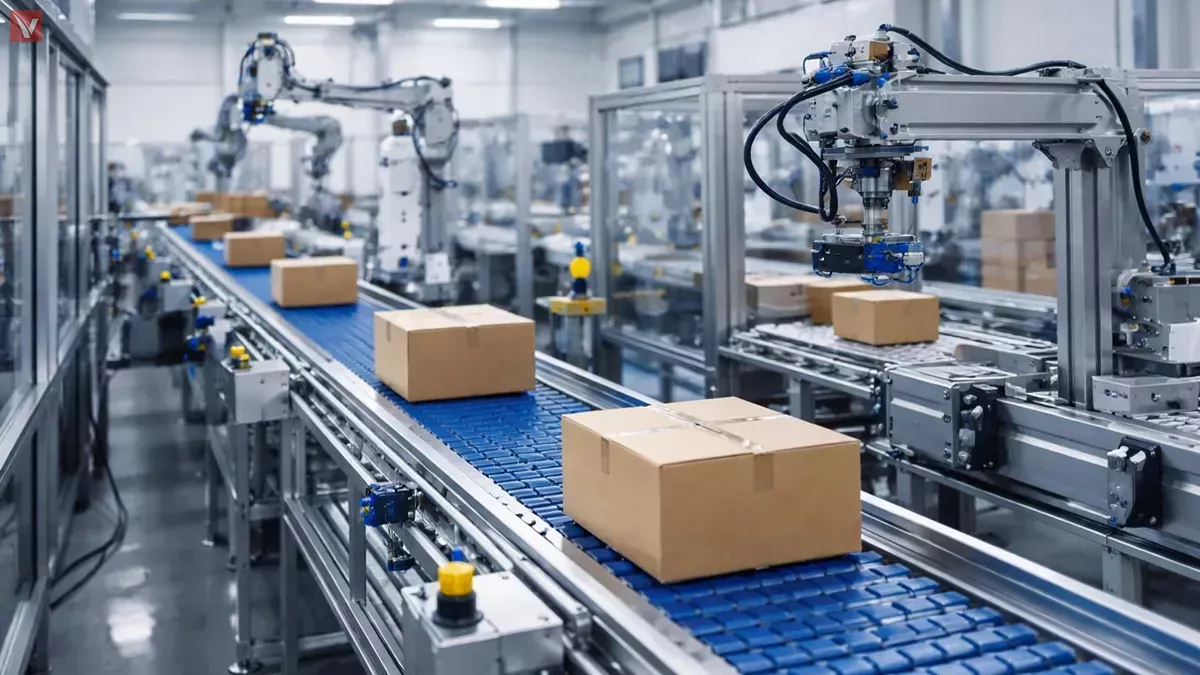
PLCs are used across industries where machines and processes require automatic monitoring, sequencing, or control.
| Industry | Common PLC applications |
|---|---|
| Manufacturing | Assembly lines, machine sequencing, material handling |
| Automotive | Automated assembly, robotic cell coordination, testing |
| Food and Beverage | Filling, packaging, temperature control |
| Water Treatment | Pump control, tank-level monitoring, valve operation |
| Energy | Auxiliary equipment monitoring, process control |
| Logistics | Conveyor systems, sorting and automated handling |
| HVAC | Fan control, temperature management, equipment sequencing |
In water treatment facilities, for example, a PLC may receive level measurements from a tank and automatically start or stop pumps according to programmed thresholds. Analog inputs can provide continuous level information, while digital outputs communicate operating commands to motor starters or drives.
In packaging operations, PLCs coordinate sensors, conveyor motors, actuators, and timing sequences to maintain consistent production cycles.
Although the applications differ, the fundamental principle remains the same: the controller reads field information, processes programmed instructions, and controls equipment accordingly.
Advantages and Limitations of PLCs
PLCs are widely adopted because they provide dependable industrial control while allowing machine behavior to be modified through software.
Their industrial construction makes them suitable for demanding operating environments. Programmable logic also reduces the need for extensive rewiring when modifying control sequences. Built-in diagnostics, communication functions, and modular expansion options can simplify troubleshooting and future system upgrades.
Compared with traditional relay-based control, PLC systems can make complex sequencing and timing functions more manageable.
However, PLCs have limitations. Hardware, software licenses, engineering time, and maintenance requirements can increase overall system costs. Some platforms use proprietary programming environments, and compatibility between different manufacturers is not guaranteed.
For simple control tasks, a dedicated relay or standalone controller may be more economical. Conversely, highly specialized computing or motion-control applications may require additional controllers or integrated automation platforms.
PLC vs. Relay Logic, Microcontrollers, and PACs
Although PLCs are versatile, they are not the only option for industrial control. Understanding the alternatives helps engineers select an appropriate control architecture.
| Controller | Key characteristics | Common applications |
|---|---|---|
| PLC | Industrial durability, programmable logic, standardized I/O options | Machine and process automation |
| Relay Logic | Hardwired switching and control | Simple, fixed control functions |
| Microcontroller | Compact embedded processing with customizable electronics | Embedded products and specialized devices |
| PAC | Often emphasizes integrated, complex, or multi-domain automation | Advanced industrial control systems |
A PLC is generally easier to integrate into conventional industrial control panels than a custom microcontroller-based design. Relays remain useful for straightforward switching functions, while PACs may offer broader processing and integration capabilities.
The distinction between PLCs and programmable automation controllers (PACs) is not always strict. Modern high-performance PLCs can provide many functions traditionally associated with PACs, so actual product specifications are more meaningful than category names alone.
How to Choose the Right PLC for Your Application
Selecting a PLC requires matching the controller's capabilities to the machine's electrical and operational requirements. The following factors provide a practical starting point.
Determine the Required Number of I/O Points
Begin by identifying every sensor, switch, actuator, and controlled device. Count the required digital and analog inputs and outputs separately, then consider additional capacity for future modifications.
For example, a small conveyor with two sensors, two push buttons, a motor run command, and two indicator lights may require at least four digital inputs and three digital outputs, assuming these functions are wired individually.
Match Voltage Levels and Signal Types
Confirm the controller's supply voltage, input voltage ranges, output ratings, and analog signal compatibility. A 24V DC sensor cannot automatically be connected to every PLC input, and an output module must be suitable for its connected load.
Evaluate Expansion and Communication Requirements
Consider whether the system needs additional I/O modules, HMI connectivity, remote monitoring, or communication with motor drives. Environmental ratings, panel space, available engineering software, technical support, and product lifecycle should also influence the final decision.
Essential Components for a Complete PLC Control System
A functioning PLC installation typically requires more than the controller itself. Supporting electrical components connect the PLC to field equipment and provide the power, switching, and communication functions needed for reliable operation.
| Component | Role in a PLC system |
|---|---|
| Sensors and switches | Provide machine status and process measurements |
| Relays and contactors | Switch or interface with electrical loads |
| Power supplies | Provide suitable power to control equipment |
| I/O modules | Connect field signals to the PLC |
| HMI panels | Display machine status and accept operator commands |
| Motor drives | Control motor operation, speed, or motion |
| Circuit protection and terminals | Support safe power distribution and wiring |
For a small automated conveyor, the component list might include a compact PLC, a 24V DC power supply, photoelectric sensors, a motor drive or contactor, protection devices, and the necessary wiring accessories.
When specifying these components, engineers should verify electrical ratings, interface compatibility, environmental conditions, and applicable safety requirements rather than selecting parts based only on product categories.
VIGOR COMPONENTS supplies a range of electronic components that can support industrial automation equipment design, maintenance, and repair projects. Explore our product offerings to find components suitable for your system requirements.
Frequently Asked Questions About PLCs
Is a PLC the same as a computer?
A PLC is a specialized industrial computer, but it is designed primarily for machine and process control. Unlike a general-purpose PC, it typically provides industrial I/O interfaces, dedicated control functions, and hardware designed for continuous industrial operation.
Can a PLC operate without a computer?
Yes. Once a PLC has been programmed and properly configured, it can generally execute its control program independently. A computer is primarily needed for programming, configuration, monitoring, and troubleshooting.
Does every PLC need programming?
Most PLCs need an application program to perform their intended control functions. Manufacturers may provide examples, templates, or preconfigured functions, but these must still be verified against the actual machine requirements.
What is the difference between a PLC and an HMI?
A PLC executes control logic and interfaces with industrial equipment. An HMI (Human-Machine Interface) allows operators to monitor processes, view alarms, and enter commands. They often work together but serve different functions.
How long does a PLC last?
Industrial PLCs can operate for many years under suitable conditions. Their service life depends on factors such as operating temperature, electrical conditions, component quality, maintenance, and manufacturer support. Product availability and software compatibility may become concerns before the hardware itself fails.
Conclusion
A programmable logic controller is a key building block of industrial automation. By collecting input signals, executing programmed instructions, and controlling outputs, PLCs enable machines to perform repetitive operations with consistency and flexibility.
Understanding PLC working principles, components, programming, and applications provides a foundation for designing and maintaining automated systems. Choosing the right controller also requires careful attention to I/O capacity, electrical specifications, communication capabilities, and supporting hardware.
Whether developing a new machine or maintaining an existing production line, a well-matched PLC and properly selected industrial control components are essential for a reliable automation system.