
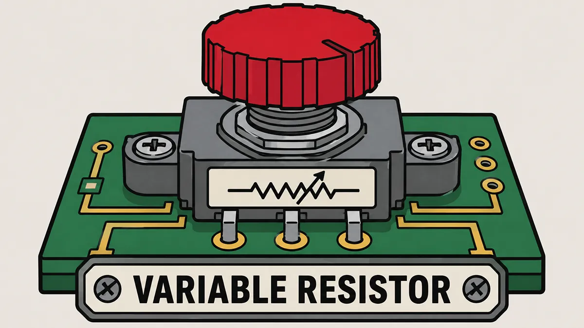
In the intricate world of electronic hardware design, controlling the flow of electricity is the fundamental basis of all circuit functionality. Whether you are tuning the precise output voltage of a power supply, adjusting the operating bias of a transistor amplifier, or simply lowering the volume on an audio interface, dynamic control is essential. This is where adjustable resistive components become indispensable.
For hardware engineers, procurement specialists, and tech hobbyists alike, understanding the nuances of these components can mean the difference between a stable, long-lasting circuit and catastrophic thermal failure. In this comprehensive technical guide, we will break down the physical architecture of these components, clarify the often-confusing terminology used in manufacturer datasheets, and explore exactly how to select and source the right parts for your printed circuit board (PCB).
What Is a Variable Resistor
At its most fundamental level, a variable resistor is a passive electro-mechanical transducer that allows its electrical resistance value to be adjusted dynamically, rather than having a fixed, constant value. To understand how it achieves this, we have to look closely at its internal physical structure, which primarily consists of two critical elements: the resistive track and the wiper. Implementing these adjustable components within electron devices and circuits enables precise calibration of voltage and current.
The resistive track (or element) is the stationary part of the component. It is manufactured from materials with specific resistive properties, such as carbon composition, conductive plastic, ceramic-metal mixtures (cermet), or coiled resistance wire (wirewound). This track provides the total maximum resistance of the component.
The wiper (or sliding contact) is the mechanical heart of the device. It is a movable metallic contact that physically slides or rotates along the surface of the resistive track. Because electrical resistance is directly proportional to the length of the resistive material the current must travel through \(R = \rho \frac{L}{A}\), moving the wiper effectively shortens or lengthens the electrical path. When you turn a knob or slide a fader, you are mechanically repositioning this wiper, thereby changing the resistance between the wiper terminal and the ends of the track in real-time. This foundational physical mechanism serves as the cornerstone for all adjustable resistive devices across the electronics industry.
What Is Another Term for a Variable Resistor
When navigating engineering forums or parsing through legacy schematics, beginners often ask: what is another term for a variable resistor? In standard industry parlance, the terms potentiometer (frequently abbreviated as "pot") and rheostat are the most common alternative terms used to describe this component. However, this linguistic interchangeability often leads to confusion.
To understand the potentiometer vs variable resistor debate, we must look at how engineers communicate in the real world. Strictly speaking, a variable resistor is the broad, overarching category for any resistor that can change its value. However, because the potentiometer is by far the most ubiquitous iteration of this technology found in consumer electronics, the term has undergone a semantic shift. Engineers and technicians frequently use the specific representative product (the potentiometer) as a synecdoche to refer to the entire overarching category.
Furthermore, the underlying physical architecture of a potentiometer and a generic variable resistor are completely identical. Both contain the exact same resistive element, the same housing, and the same mechanical wiper. The only physical difference lies in how they are integrated into a broader electrical circuit, which leads us to their technical classifications.
What Are the Three Common Types of Variable Resistors
While interchangeable in casual laboratory conversation, the precise wiring configuration on a printed circuit board dictates a strict functional classification. If you are asked what are the three common types of variable resistors, the rigorous engineering answer is categorized by their terminal connections and intended lifecycle: Potentiometers, Rheostats, and Trimpots.
Understanding the rheostat vs potentiometer distinction is particularly critical when calculating power dissipation and thermal management on your BOM (Bill of Materials).
1. The Potentiometer (Voltage Divider)
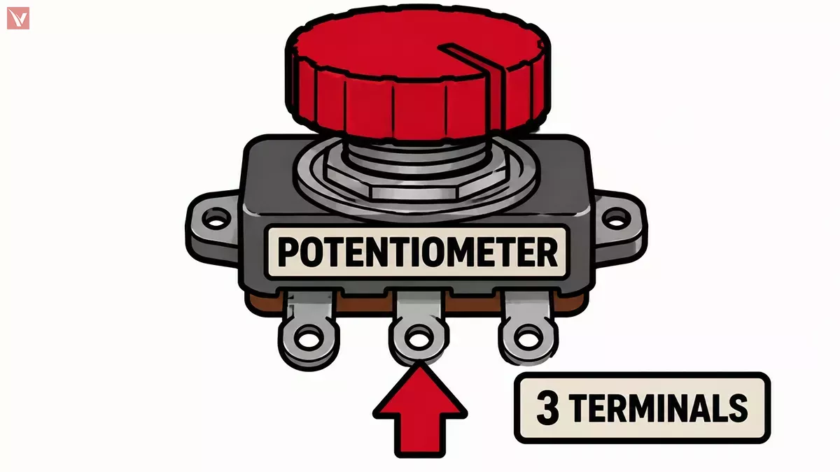
A potentiometer utilizes all three of its physical terminals: the two outer terminals connected to the ends of the resistive track, and the middle terminal connected to the movable wiper. In this configuration, the component acts as a variable voltage divider. The input voltage is applied across the entire track (the two outer pins), and the output voltage is tapped from the wiper. As the wiper moves, it continuously adjusts the ratio of resistance on either side of it, smoothly dividing the voltage without changing the total resistance presented to the power source.
2. The Rheostat (Current Controller)
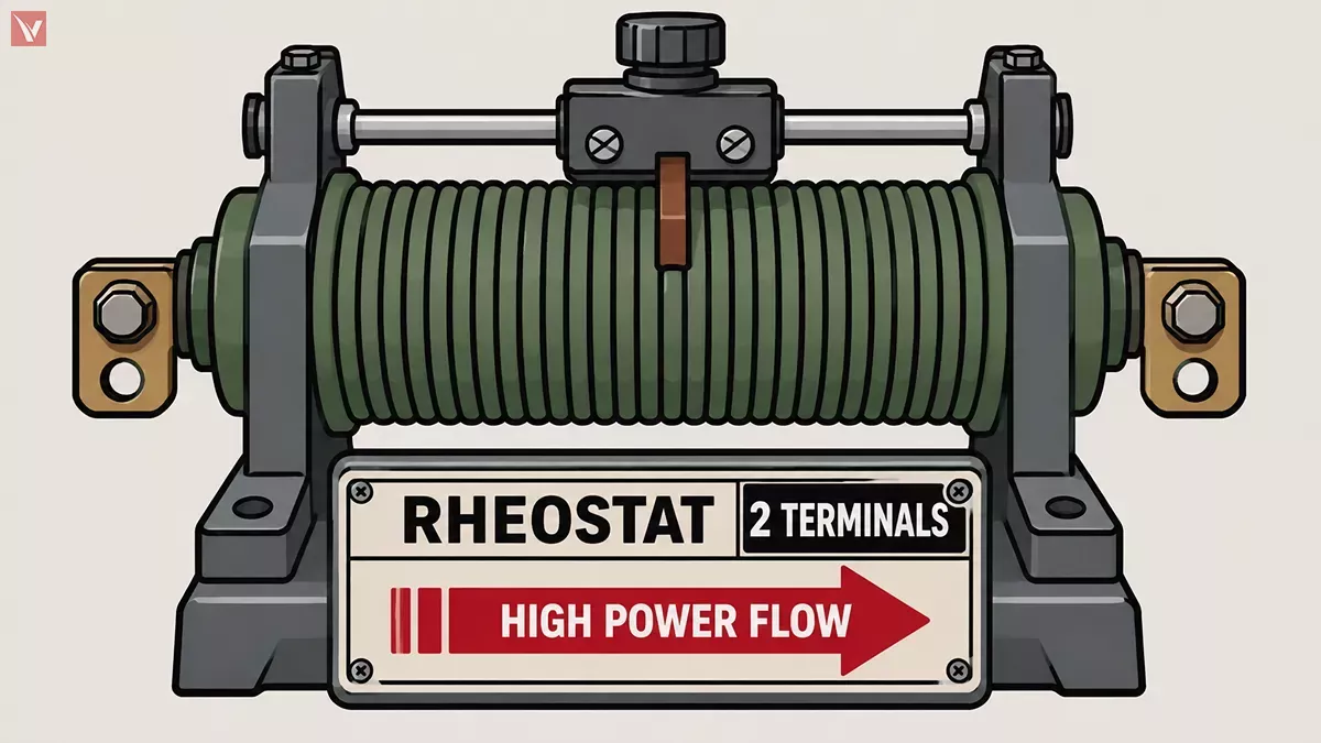
Unlike the 3-terminal setup, a rheostat is wired using only two terminals: one end of the resistive track and the movable wiper. By placing this 2-terminal setup in series with a load, the rheostat acts as a variable current limiter. Because all the load current must physically pass through the wiper and the track, rheostats are typically subjected to much higher thermal stress. For this reason, true rheostats are usually constructed as heavy-duty wirewound components designed to dissipate significant heat (measured in watts), making them visibly larger and more rugged than standard potentiometers.
3. The Trimpot (Set and Forget)
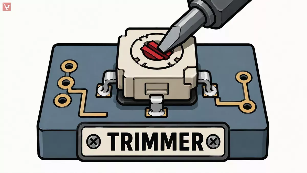
Trimmer potentiometers, universally known as "trimpots," are miniaturized variable resistors designed to be mounted directly onto a PCB. While they usually possess three terminals like a standard potentiometer, their usage lifecycle is entirely different. Instead of featuring a user-accessible knob, trimpots have a small slot meant to be adjusted with a specialized screwdriver during factory calibration. Known in the industry as "set and forget" components, they are used to tune out component tolerances, calibrate sensor thresholds, or adjust the bias of an op-amp before the device casing is permanently sealed.
Standard Variable Resistor Symbol Guide
Reading schematic diagrams requires a firm grasp of international standardizations. Because the electronics industry is global, you will frequently encounter different visual representations depending on the origin of the schematic. A proper variable resistor symbol guide must account for both European/International and North American drawing conventions.
The IEC 60617 standard (International Electrotechnical Commission) relies on a rectangular block to denote a resistor, whereas the IEEE 315 / ANSI Y32.2 standard (widely used in the US and legacy schematics) utilizes a zigzag line. To denote variability, a diagonal arrow is drawn through or pointing to the base symbol.
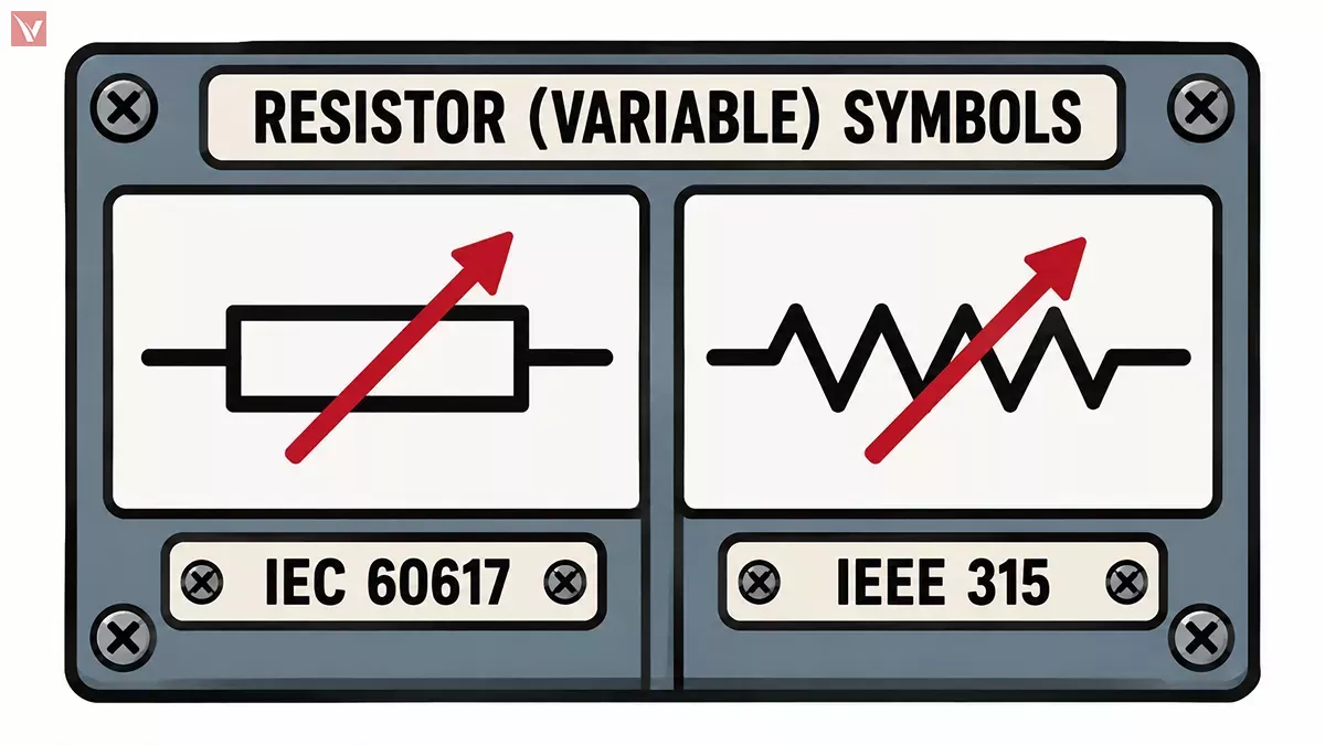
Furthermore, the schematic must explicitly show whether the component is wired as a 3-pin voltage divider or a 2-pin current limiter.
| Component Type | Standard & Region | Base Symbol Shape | Indicator of Variability |
|---|---|---|---|
| Variable Resistor (Generic) | IEC 60617 (International) | Rectangular box | Diagonal arrow striking through the center of the box. |
| Variable Resistor (Generic) | IEEE / ANSI (USA) | Zigzag line | Diagonal arrow striking through the center of the zigzag. |
| Potentiometer (3-Pin) | IEC / IEEE Universally | Rectangle OR Zigzag | An arrow pointing perpendicularly to the middle of the resistor body, representing the wiper terminal. |
| Rheostat (2-Pin) | IEC / IEEE Universally | Rectangle OR Zigzag | One end of the resistor is unconnected, while the wiper arrow acts as the second active terminal. |
| Trimpot (Preset) | IEC / IEEE Universally | Rectangle OR Zigzag | A "T" shaped line or a flat-ended line intersecting the resistor body instead of a pointed arrow. |
By identifying the number of active connection points shown in the symbol, an engineer can immediately deduce whether the component is meant to regulate potential (voltage) or restrict flow (current).
What a Variable Resistor Is Commonly Used To Control
Moving from theoretical physics to practical engineering, the applications for these components span every sector of the electronics industry. What a variable resistor is commonly used to control depends entirely on its wiring configuration and logarithmic or linear taper.
Typical application scenarios include:
Audio Signal and Volume Control: Audio amplifiers utilize 3-terminal potentiometers with a logarithmic taper to adjust volume. Because human hearing responds to sound intensity logarithmically, the resistive track is manufactured to increase resistance on a curve, ensuring smooth, natural-sounding volume adjustments.
Current Limiting and Motor Speed: High-wattage rheostats are wired in series with DC motors or industrial lighting systems. By dynamically increasing the resistance in the path of the current, they throttle the electrical flow, thereby dimming heavy-duty lights or slowing down the rotational RPM of industrial machinery.
Sensor Calibration and Tuning: Precision multi-turn trimpots are embedded into circuits connected to temperature sensors, strain gauges, and optical detectors. Engineers use these components to manually adjust reference voltages, ensuring that analog-to-digital converters (ADCs) receive perfectly calibrated baseline signals despite minor manufacturing variances in other nearby components.
Sourcing Quality Variable Resistors with Vigor Components
One of the most persistent pain points in electronics manufacturing and PCB assembly is procurement errors caused by ambiguous datasheets. Because manufacturers often mix the terms "potentiometer" and "rheostat," junior buyers frequently source 3-pin voltage dividers for applications that require heavy-duty 2-pin current limiters. This results in burned-out tracks, failed quality assurance tests, and costly production line delays. The physical footprint, maximum power dissipation (wattage), and wiper current limits must be strictly verified before purchasing.
This is where working with a specialized partner becomes invaluable. Vigor Components operates as a premier global independent electronic components distributor, bridging the gap between raw supply chain logistics and deep technical engineering support.
When you source passive components through Vigor Components, you gain access to an expert team capable of conducting rigorous cross-reference checks. Whether you are dealing with obsolete trimpots, require exact footprint matches for high-power rheostats, or need to verify the lifecycle status of a specific Bourns or Vishay potentiometer, our technical team ensures your BOM is flawless. Furthermore, our stringent anti-counterfeit testing protocols and robust spot-market inventory ensure that your production line remains stable, secure, and supplied with genuine, high-quality components.
References
- International Electrotechnical Commission. (2012). IEC 60617: Graphical Symbols for Diagrams. IEC Webstore.
- Institute of Electrical and Electronics Engineers. (1975). IEEE 315-1975: Graphic Symbols for Electrical and Electronics Diagrams. IEEE SA.
- TE Connectivity. Variable Resistors Overview and Applications. TE Connectivity Official Portal.
- Bourns, Inc. Trimpot® Trimming Potentiometers Technical Library. Bourns Official Website.