
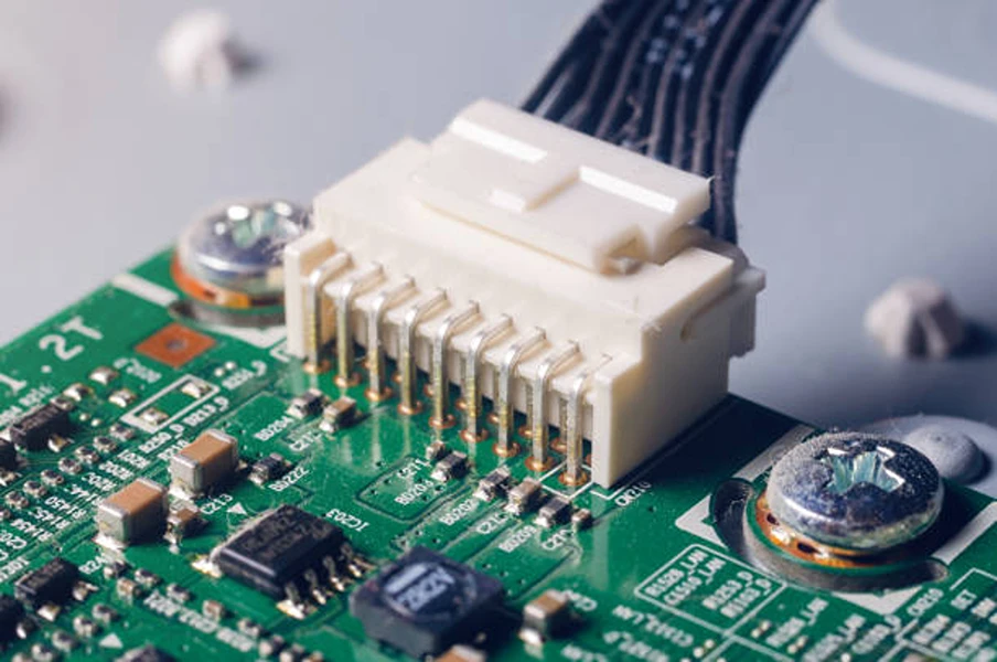
Board-to-Board vs. Wire-to-Board Connectors Overview
Choosing between a board to board vs wire to board connector comes down to balancing spatial constraints, signal integrity, mechanical tolerance, and assembly labor. Board-to-board (BTB) connectors join two printed circuit boards (PCBs) directly through rigid mating housings, eliminating cable harnesses and supporting compact, high-speed layouts. Wire-to-board (WTB) connectors link discrete wires or pre-assembled cables to a PCB header, providing routing flexibility, wider mechanical tolerances, and reliable performance in high-vibration or higher-current environments.
| Feature | Board-to-Board (BTB) Connectors | Wire-to-Board (WTB) Connectors |
|---|---|---|
| Connection Method | Direct rigid mating between two PCB-mounted housings | PCB header mated with a wire-mounted plug housing |
| Typical Pitch Range | 0.35 mm to 2.54 mm (up to 5.08 mm for power) | 1.00 mm to 5.08 mm+ |
| Signal & Current Focus | Short trace paths for high-speed data and high pin counts | Flexible wire gauge selection for power and off-board signals |
| Mechanical Tolerance | Strict PCB alignment required (unless using floating BTB) | Flexible wires naturally absorb vibration and board misalignment |
| Assembly Process | Automated surface-mount (SMT) or through-hole soldering | PCB soldering plus wire stripping, crimping, and harness routing |
| BOM Part Complexity | 2 part numbers (mating receptacle and plug headers) | Typically 3+ part numbers (PCB header, housing, crimp terminals) |
What Are Board-to-Board (BTB) Connectors?
Board-to-board connectors connect two PCBs without intermediate wiring. Because the electrical path between boards is often just a few millimeters long, BTB interconnects minimize parasitic inductance and capacitance, making them well-suited for high-speed digital interfaces and space-constrained enclosures.
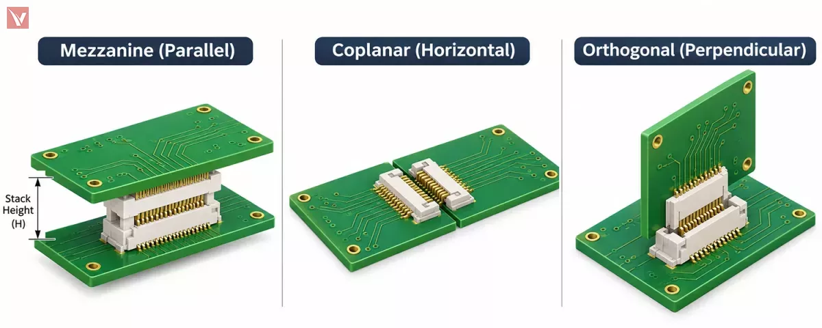
Common Configurations: Mezzanine, Coplanar, and Orthogonal
Engineers generally deploy BTB connectors in three geometric orientations:
- Mezzanine (Parallel Stacking): Two PCBs sit parallel to one another, separated by a defined stack height. Fine-pitch series such as the Molex SlimStack support mated heights as low as 0.60 mm for compact portable devices.
- Coplanar (Edge-to-Edge): Two boards sit on the same horizontal plane, allowing modular PCB expansion inside slim housings such as LED light bars or industrial display panels.
- Orthogonal (Mother-Daughter): One card plugs perpendicularly into a mainboard. High-pin-count modular systems often rely on specialized backplane connectors or standardized DIN 41612 connectors to handle multi-slot card cages.
Strengths and Mechanical Limitations of BTB Connections
While BTB connectors eliminate manual cable assembly and streamline automated pick-and-place manufacturing, their rigid mechanical coupling introduces layout constraints. Standard BTB headers allow very little positional misalignment. Placing two or more rigid BTB pairs across the same board pair can create mechanical stress on solder joints due to accumulated dimensional tolerances. When multiple board-to-board connections are required on a single PCB, engineers frequently specify floating BTB connectors that permit slight X-Y movement during mating.
What Are Wire-to-Board (WTB) Connectors?
Wire-to-board connectors bring power and signals onto a PCB from external power supplies, sensors, switches, display modules, or distant daughterboards. Many industrial WTB systems fall under the broader category of rectangular connectors, featuring insulated plastic shrouds that guide mating and prevent reverse polarity.
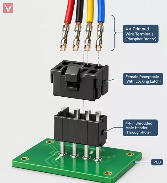
The Three-Part Assembly: PCB Header, Housing, and Crimp Terminals
Unlike BTB pairs that only require two mating part numbers, a standard crimp-style WTB interconnect requires three separate components on the bill of materials (BOM):
- PCB Header: The male pin header (vertical or right-angle, through-hole or SMT) soldered directly to the board.
- Receptacle Housing: The empty plastic plug shell that mates with the PCB header.
- Crimp Terminals: The metal contacts crimped onto stripped wires before being inserted into the plastic housing cavities.
For example, building a complete Molex Micro-Fit 3.0 connection requires specifying a PCB header (such as series 43045), a mating receptacle housing (series 43025), and compatible crimp terminals (series 43030) matched to the wire gauge.
Crimp vs. IDC Termination Methods
WTB systems primarily use either crimp or insulation displacement contact (IDC) termination. Crimp connectors strip individual wires and mechanically compress a metal terminal around the conductor and insulation, offering strong pull-out resistance and flexibility across diverse wire gauges (AWG). IDC connectors use sharp metal blades to slice through flat ribbon cable insulation in a single press operation, speeding up mass termination for lower-current signal harnesses.
Five Key Engineering Differences Between BTB and WTB Connectors
Pitch, Stack Height, and PCB Footprint
BTB connectors achieve much higher contact density because they do not need room for wire insulation or crimping barrels. Fine-pitch BTB arrays routinely operate at 0.35 mm to 0.80 mm pitch. Conversely, WTB pitch is physically constrained by the outer diameter of the wire insulation, typically starting around 1.00 mm to 1.25 mm for micro-signal headers and scaling to 2.54 mm, 3.00 mm, or 5.08 mm for power distribution.
Signal Integrity vs. Current Carrying Capacity
High-density BTB arrays excel at routing dozens or hundreds of high-speed differential or single-ended signals over short vertical paths. WTB connectors are generally preferred when delivering higher current across boards, as engineers can pair larger contact blades with heavier wire gauges (such as 18 AWG or 16 AWG). However, a connector's actual current capacity is never a single fixed number—it depends directly on the selected wire gauge, total populated circuits, and ambient temperature derating.
| Series Name | Category | Verified Pitch | Max Current Rating (Verified Condition) | Typical Use Case |
|---|---|---|---|---|
| Molex SlimStack | BTB (Mezzanine) | 0.35 mm – 1.25 mm | ~0.3 A – 1.0 A (signal); up to 18.0 A (hybrid power pins) | Compact consumer & portable industrial modules |
| Molex SEARAY | BTB (High-Density Array) | 1.27 mm | Up to 2.7 A per contact | High-pin-count computing & telecom boards |
| JST PH Series | WTB (Crimp / IDC) | 2.00 mm | 2.0 A AC/DC (verified with 24 AWG wire) | Internal battery packs, sensors, low-power signals |
| Molex Micro-Fit 3.0 | WTB (Power/Signal Crimp) | 3.00 mm | 8.5 A (2-circuit with 18 AWG); up to 10.5 A (high-current contacts) | Power distribution, industrial equipment, appliances |
| Molex KK (254 / 396) | WTB & BTB | 2.54 mm – 5.08 mm | Up to 13.0 A (varies by pitch and wire gauge) | General-purpose board power and control wiring |
Vibration Resistance, Mating Tolerance, and Locking Mechanisms
In equipment exposed to motor vibration or thermal expansion, WTB cable harnesses act as mechanical buffers that isolate solder joints from physical stress. While standard low-profile WTB series like the JST PH rely on friction locks, industrial series such as Molex Micro-Fit 3.0 incorporate positive latches that click into place and prevent accidental unmating under cable tension.
Assembly Process and Total Cost of Ownership
Evaluating total interconnect cost requires looking beyond unit component pricing. A fine-pitch BTB connector may carry a higher unit price than a basic WTB pin header, but both halves are placed automatically via SMT reflow with minimal manual labor. Conversely, WTB headers and housings are relatively inexpensive, yet they require wire cutting, terminal crimping, harness testing, and manual plug insertion during final box build.
How to Choose the Right Connector for Your PCB
Use the following engineering criteria to narrow down the right interconnect architecture:
- Select Board-to-Board (BTB) when: Enclosure height is tightly constrained, boards sit directly adjacent or stacked, high-speed signal integrity is critical, or manufacturing relies entirely on automated SMT assembly without cable installation.
- Select Wire-to-Board (WTB) when: PCBs are mounted at awkward angles or long distances, the assembly experiences continuous vibration, technicians need easy unmating for field servicing, or the interface connects off-board components like fans, displays, and power supplies.
- Avoid Cross-Brand Mating Assumptions: Even if two WTB or BTB connectors share an identical pitch (such as 2.00 mm or 2.54 mm), housings and headers from different manufacturers are generally not drop-in intermateable. Variations in shroud polarization ribs, pin lengths, and terminal lance geometries can cause intermittent contact or housing damage. When substituting brands, qualify the complete mated set (header, housing, and crimp terminals) together.
Wire-to-Board Connector Factory vs. Distributor Sourcing
Once the engineering team locks in the connector specifications, purchasing teams often weigh wire to board connector factory vs distributor channels. Each sourcing route serves different production volumes and BOM structures.
| Sourcing Factor | Direct Connector Factory | Electronic Component Distributor |
|---|---|---|
| Minimum Order Quantity (MOQ) | High (crimp terminals often sold in full reels of 5,000–10,000+ pcs) | Flexible (supports prototype quantities, cut tape, and full reels) |
| Complete Kit Matching | Buyer must manually track separate header, housing, and terminal SKUs | Helps verify and bundle matching headers, housings, and AWG terminals |
| Multi-Brand BOM Consolidation | Limited to a single manufacturer's catalog | Consolidates Molex, JST, TE, Amphenol, and passives on one PO |
| Custom Tooling & Harnesses | Ideal for custom overmolding or high-volume pre-assembled harnesses | Primarily supplies standard off-the-shelf interconnect components |
When Direct Factory Sourcing Makes Sense
Working directly with a connector manufacturer or specialized cable assembly factory is practical for high-volume mass production where designs are frozen and annual consumption easily clears full-reel MOQs. Direct factory engagement is also necessary when an enclosure requires custom-tooled housing geometries or pre-wired custom cable harnesses.
Why Buyers Use Component Distributors for Multi-Part BOMs
During prototyping, pilot runs, and medium-volume production, sourcing through an electronic component distributor reduces procurement friction. Because a single PCB often combines fine-pitch BTB arrays, power WTB headers, and dozens of active ICs, consolidating orders through a distributor avoids managing multiple factory vendor accounts. More importantly, experienced distributors help purchasing teams cross-check BOM line items to ensure mating housings and correct wire-gauge crimp terminals are not accidentally omitted.
If you are preparing a multi-part interconnect BOM or comparing lead times across BTB and WTB series, you can submit your part list to Vigorcomp for coordinated BOM quoting and sourcing support.
Contact US
Frequently Asked Questions
Why do wire-to-board connectors require separate part numbers for housings and terminals?
Manufacturers sell plastic receptacle housings and metal crimp terminals separately so one housing family can support multiple wire gauges (such as 20 AWG vs. 26 AWG) and contact plating options (tin vs. gold) without changing the plastic shell. Always verify that all three-part numbers—header, housing, and terminal, are included in your BOM.
Can I mate a 2.0 mm pitch connector from one manufacturer with another brand's 2.0 mm header?
Generally, no. Sharing a nominal 2.0 mm pitch does not guarantee mechanical or electrical compatibility. Differences in housing wall thickness, locking ramps, and contact wiping lengths can lead to loose connections or bent pins.
What determines the actual current rating of a wire-to-board connector?
The maximum current listed on a series overview page typically reflects a 2-circuit housing wired with the thickest supported conductor. Using thinner wires, populating more adjacent pins in the same housing, or operating at high ambient temperatures will reduce the allowable current per contact.
When should I use a floating board-to-board connector?
Floating BTB connectors are recommended whenever two PCBs are joined by multiple BTB connectors simultaneously, or in automotive and industrial systems where vibration and assembly tolerances could stress rigid solder joints.