Why Electrical Schematic Symbols Matter
Electrical schematic symbols are the visual language of circuits. They let engineers, technicians, buyers, and maintenance teams discuss the same circuit without depending on product photos, mounting layout, or brand-specific drawings.
What Are Electrical Schematic Symbols
Electrical schematic symbols are simplified graphic marks used to represent components, terminals, conductors, and functional relationships in a circuit. In a proper schematic, the symbol tells you what the device does in the circuit, not what the real part looks like on the bench.
Electrical Symbols vs Electronic Symbols
In practice, electrical symbols are used more often for power distribution, motors, relays, breakers, and industrial controls, while electronic symbols more often describe semiconductors, logic, ICs, and low-voltage signal paths. Modern schematics often mix both categories because industrial equipment commonly includes power, control, and embedded electronics in one design.
The Role of Schematics in Design, Manufacturing, and Maintenance
A schematic helps the design team define function, the manufacturing team verify connectivity, and the maintenance team troubleshoot faults quickly. It is especially valuable because a well-drawn schematic separates logical operation from physical placement, which makes complex systems easier to inspect and modify.
Why Standardized Symbols Matter
Standardization reduces interpretation errors across countries, companies, and software libraries. Public reference material for IEC symbol families and IEEE/ANSI symbol usage shows that common categories such as switches, relays, transformers, motors, terminals, and semiconductor devices are organized into consistent symbol groups rather than ad hoc drawings.
Understanding IEC and ANSI Symbol Standards
IEC and ANSI symbol systems aim at the same goal: consistent circuit communication. In daily engineering work, the most important point is not memorizing every line shape, but knowing which standard the drawing follows and reading it consistently.
| Topic | IEC Practice | ANSI / IEEE Practice | Reader Note |
|---|---|---|---|
| Primary reference | Commonly associated with IEC symbol libraries such as IEC 60617 families | Commonly associated with IEEE/ANSI 315 graphic symbols | Check the title block, legend, or CAD library before comparing symbols. |
| Typical usage | Common in Europe and in multinational OEM documentation | Common in U.S.-oriented documentation and legacy North American practice | Global projects may contain both styles in different files. |
| Visual differences | Often favors cleaner geometric forms, such as the rectangular resistor | Often favors familiar legacy forms, such as the zigzag resistor | Function is the same even when the graphic shape changes. |
| Industrial control coding | Cross-reference sheets often use IEC device codes such as KM, KA, SB, QF, and FU | The same sheets may also show older ANSI-style abbreviations beside them | This is useful when reading panels, PLC schematics, and machine wiring. |
IEC Overview
IEC symbol libraries group devices into structured families, including push buttons, circuit breakers, fuses, transformers, relays and contacts, motors, generators, terminals, sensors, and semiconductor components. That breadth is one reason IEC-style documentation is widely used in industrial and international projects.
ANSI Overview
IEEE/ANSI 315 defines regulated graphic symbols for electrical and electronic diagrams, and official descriptions note that the symbols are designed on a modular grid to support consistent drafting. In practice, many U.S. libraries and EDA platforms still reference this tradition for contacts, switches, relays, connectors, inductors, and transformers.
Global Usage Differences
The cleanest rule is simple: follow the standard that the drawing set declares. Mixed environments are common, especially when a U.S. controls package, a European machine builder, and a global component supplier all contribute to the same documentation set.
Most Common Electrical Schematic Symbols
This group covers the symbols that appear first in basic power and control diagrams. They are the symbols most beginners should learn before moving into semiconductors and logic.
| Typical Symbol Form | Component | Function | Symbol |
|---|---|---|---|
| Break in a line with movable contact | Switch | Manually opens or closes a circuit path. | |
| Momentary contact symbol, often labeled NO or NC | Push Button | Provides temporary control input. | |
| Lamp or indicator circle | Lamp | Shows status or provides illumination. | |
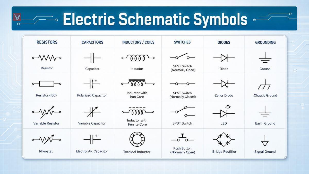
| Coil with associated contacts | Relay | Uses an energized coil to switch one or more contacts. | 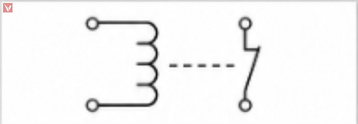 |
| Heavier-duty relay / power switching symbol | Contactor | Switches larger currents, often for motors or heaters. |  |
| Protective element inserted in series | Fuse | Opens the circuit when current exceeds its rating. | |
| Protective switching device | Circuit Breaker | Interrupts fault current and can usually be reset. | |
| Motor load symbol | Motor | Converts electrical energy into mechanical motion. | |
| Coupled windings | Transformer | Transfers power between circuits by magnetic coupling. | |
| Reference ground symbol | Ground | Defines the common return or reference point. |  |
Industrial symbol libraries and quick-reference documents consistently include these device families, especially push buttons, relays, circuit breakers, fuses, transformers, motors, and terminals. That is why they form the core vocabulary of maintenance schematics, panel drawings, and machine control diagrams.
Passive Component Symbols
Passive components do not amplify or switch by themselves. They shape current, voltage, timing, filtering, and energy storage.
| Component | Function | Typical IEC Symbol | Typical ANSI Symbol |
|---|---|---|---|
| Fixed Resistor | Limits current or creates a voltage drop. | Rectangle | Zigzag line |
| Variable Resistor | Adjusts resistance manually or mechanically. | Rectangle with diagonal adjustment arrow | Zigzag with diagonal adjustment arrow |
| Potentiometer | Provides an adjustable voltage divider. | Resistor with center wiper terminal | Resistor with center wiper terminal |
| Non-Polarized Capacitor | Stores charge; often used for coupling, timing, or filtering. | Two parallel plates | Two parallel plates |
| Polarized Capacitor | Stores charge with polarity-sensitive installation. | Plate pair with polarity mark | Plate pair, often with curved negative side or polarity mark |
| Variable Capacitor | Allows adjustable capacitance. | Capacitor with diagonal arrow | Capacitor with diagonal arrow |
| Air-Core Inductor | Stores energy in a magnetic field. | Coil only | Coil only |
| Iron-Core Inductor | Provides higher inductance using a magnetic core. | Coil with parallel core lines | Coil with parallel core lines |
| Variable Inductor | Allows inductance adjustment. | Coil with diagonal arrow | Coil with diagonal arrow |
Resistor Symbols
The resistor is the first symbol family where IEC and ANSI differences become obvious to beginners. If you see a rectangle, think IEC-style resistor; if you see a zigzag, think ANSI-style resistor.
Capacitor Symbols
Capacitor symbols are usually easy to recognize because both standards keep the two-plate concept. The critical reading skill is not the plate shape, but whether polarity or adjustability is marked.
Inductor Symbols
Inductors are usually drawn as coils, with added core lines for magnetic material. In transformer-related designs, it is useful to read inductors and coupled windings as the same magnetic-language family.
Semiconductor Symbols
Semiconductor symbols are more functional than pictorial. Once you understand the direction of current intent, polarity marks, and optical arrows, the symbols become much easier to read.
| Component | Function | Typical Symbol Cue | Reading Tip |
|---|---|---|---|
| Rectifier Diode | Allows current primarily in one direction. | Diode junction with anode and cathode | Read the cathode bar first. |
| Zener Diode | Provides voltage regulation or reference behavior in reverse bias. | Diode symbol with modified cathode line | Usually used for clamping or reference tasks. |
| Schottky Diode | Offers fast switching and low forward drop. | Diode symbol with variant cathode styling | Common in power conversion and RF support circuits. |
| TVS Diode | Suppresses transient overvoltage events. | Protection-oriented diode variant | Often placed near inputs, power rails, or connectors. |
| LED | Emits light when forward biased. | Diode symbol with arrows pointing outward | Outward arrows mean light leaving the device. |
| Infrared LED | Emits infrared radiation. | LED form, often labeled IR | Function is optical even when the light is not visible. |
| Photodiode | Converts light into current. | Diode symbol with arrows pointing inward | Inward arrows mean light arriving at the device. |
Diode Symbols
For any diode family, start by finding the cathode side. That single habit makes rectifiers, Zeners, Schottkys, and many protection diodes much easier to identify correctly.
LED and Photodiode Symbols
Arrow direction is the key visual clue. On LEDs the arrows point away from the junction because light is emitted, while on photodiodes the arrows point toward the junction because light is received.
Transistor and MOSFET Symbols
Transistor symbols reward careful reading. The main task is to identify the device family first, then read arrow direction, channel type, and mode.
| Component | Function | Typical Symbol Cue | Identification Rule |
|---|---|---|---|
| NPN Transistor | Current-controlled BJT for switching or amplification. | Emitter arrow points out | "NPN = Not Pointing iN" is a common memory aid. |
| PNP Transistor | Complementary BJT for switching or amplification. | Emitter arrow points in | Read emitter arrow before reading the rest of the symbol. |
| N-Channel MOSFET | Voltage-controlled transistor, common in low-side switching. | N-channel field-effect transistor form | Check channel label or source/body arrow convention used in the library. |
| P-Channel MOSFET | Voltage-controlled transistor, common in high-side switching. | P-channel field-effect transistor form | Read together with source orientation and gate connection. |
| Enhancement-Mode MOSFET | Normally off at zero gate bias. | Broken or separated channel style in many libraries | Most common power MOSFET schematic form. |
| Depletion-Mode MOSFET | Normally on at zero gate bias. | Solid channel style in many libraries | Less common; always confirm the drawing legend. |
| IGBT | Combines MOS gate drive with bipolar power conduction. | MOS-controlled power transistor form | Common in inverters, motor drives, and high-power switching. |
Bipolar Junction Transistor (BJT) Symbols
For BJTs, the emitter arrow does most of the work. If the arrow points out, it is NPN; if the arrow points in, it is PNP.
MOSFET Symbols
For MOSFETs, read three things in order: channel type, enhancement or depletion mode, and source/drain orientation. Exact artwork can vary slightly by library, so labels and context still matter.
IGBT Symbols
An IGBT should be read as a power-switching device with MOS-style gate control. In motor control and power electronics, it often appears where a plain small-signal transistor would be inadequate.
Integrated Circuit and Logic Symbols
IC and logic symbols compress a large amount of function into simple blocks. The symbol usually emphasizes pins and logic behavior rather than the internal transistor-level structure.
| Component | Function | Typical Symbol Form | Reading Tip |
|---|---|---|---|
| Op-Amp | Amplifies the difference between two inputs. | Triangle with + and - inputs | Check supply pins if the schematic shows them explicitly. |
| Comparator | Compares two voltages and switches the output state. | Triangle similar to op-amp | Look for threshold or reference connections. |
| AND | Outputs true only when all inputs are true. | Logic gate block | Read from input side to output side. |
| OR | Outputs true when any input is true. | Curved logic gate block | Useful in permissive control logic. |
| NOT | Inverts the input state. | Triangle with output bubble | The bubble means inversion. |
| NAND | AND followed by inversion. | AND gate with output bubble | The bubble is the key clue. |
| NOR | OR followed by inversion. | OR gate with output bubble | Very common in logic simplification. |
| XOR | Outputs true when inputs differ. | OR-like gate with extra input curve | Common in comparison and sum logic. |
| MCU | Provides programmable control and interfaces. | Labeled rectangular IC block | Pin names matter more than outer shape. |
| EEPROM | Stores non-volatile data. | Memory IC block | Look for serial or parallel interface labels. |
| SRAM | Provides fast volatile memory. | Memory IC block | Often tied to processor buses. |
| DRAM | Provides dense volatile memory. | Memory IC block | Typically part of larger digital systems. |
| Generic IC | Represents a packaged active device. | Rectangle with named pins | Always read the pin labels and part number. |
Operational Amplifier Symbols
Op-amp and comparator symbols often look similar at first glance. The difference is mostly functional: an op-amp is usually used in analog closed-loop behavior, while a comparator is used for threshold decisions.
Logic Gate Symbols
Logic gates are easiest to read from left to right. Any small circle, often called a bubble, indicates inversion at that pin.
Microcontroller and Memory Symbols
For MCU and memory symbols, the box itself is less informative than the pin naming. For electronics-components content, that is important because buyers and engineers often search by interface, voltage family, package, and memory role rather than by generic symbol shape.
Power Supply and Ground Symbols
Power and ground symbols define reference, distribution, and return paths. Misreading them causes some of the most common schematic interpretation errors.
| Component | Function | Typical Symbol Form | Application Note |
|---|---|---|---|
| DC Power | Provides steady-polarity supply voltage. | Labeled supply node, rail, or terminal | Watch the polarity marks and rail names. |
| AC Power | Provides alternating supply voltage. | AC source symbol or sinusoidal marking | Common in mains-fed equipment. |
| Battery | Provides stored DC energy. | Alternating long and short plates | Longer plate conventionally indicates the positive side. |
| Earth Ground | Connects to protective earth. | Ground bars decreasing in width | Used for safety and fault current reference. |
| Chassis Ground | Connects to frame or enclosure. | Ground variant linked to mechanical structure | Not always the same as signal ground. |
| Signal Ground | Provides reference for low-level signals. | Ground node with signal context | Helps reduce noise interpretation errors. |
| Digital Ground | Reference for digital switching currents. | Ground node labeled DGND | May be separated from AGND in mixed-signal systems. |
| Analog Ground | Reference for analog circuitry. | Ground node labeled AGND | Used to control noise and measurement stability. |
DC Power Symbols
DC supply symbols should be read together with their labels, such as +24V, +5V, VBAT, or VCC. In troubleshooting, the label often matters more than the shape.
AC Power Symbols
AC power symbols usually mark mains or alternating sources. Always read them alongside voltage, frequency, and safety context.
Battery Symbols
Battery symbols are easy to recognize because of the alternating plate lengths. They are common in portable electronics, backup supplies, and low-voltage control systems.
Ground Symbols
Different ground symbols exist because not every return path serves the same purpose. Earth ground is about safety, chassis ground is about the enclosure or frame, and signal, digital, and analog grounds are about reference integrity inside the circuit.
Circuit Protection Symbols
Protection symbols show where the designer expects fault energy, overload, or transient stress. These symbols are essential when evaluating safety, field reliability, and serviceability.
| Component | Function | Typical Symbol Cue | Typical Placement |
|---|---|---|---|
| Fuse | Sacrificial overcurrent protection. | Series protective element | Near the source or branch entry. |
| Circuit Breaker | Resettable overcurrent interruption. | Protective switching device | Feeders, branches, machines, and panels. |
| Surge Protection Device | Clamps transient overvoltage. | Protection device tied across line(s) | Inputs, power rails, communication ports. |
| Thermal Protector | Responds to excess temperature. | Temperature-linked protective device | Motors, power supplies, transformers, heaters. |
Quick-reference industrial documentation explicitly includes protective fuse notation and device tagging, which is why fuse symbols remain foundational in both panel and PCB-adjacent schematics. In reading practice, treat every fuse as a deliberate statement about fault isolation and service strategy.
Circuit Breaker Symbols
IEC symbol libraries include circuit breaker families, and industrial reference sheets cross-reference breaker notation as part of normal controls documentation. Breakers matter because they combine protection with a switching function.
Surge Protection Devices
Surge protection devices are often overlooked by beginners because their symbols vary more than basic fuses. The useful reading habit is to look for protection elements connected across vulnerable lines, especially near connectors and incoming power.
Thermal Protection Devices
Thermal protectors appear where overheating is more dangerous than short-duration overcurrent alone. They are common in motors, transformers, and power conversion assemblies.
Control Circuit Symbols for Switches and Relays
This section is especially relevant for industrial automation, machine wiring, and panel work. It is also where IEC and ANSI cross-reference charts become most practical for daily reading.
| Component | Function | Typical Symbol Form | Reading Tip |
|---|---|---|---|
| SPST Switch | Single-pole, single-throw on/off control. | One pole, one switching path | Basic two-state manual control. |
| SPDT Switch | Single-pole changeover switching. | One common terminal, two output paths | Common in selection functions. |
| DPST Switch | Switches two poles together. | Two linked SPST contacts | Used where two lines must open together. |
| DPDT Switch | Two-pole changeover switching. | Two linked SPDT contacts | Useful for polarity reversal or dual-path selection. |
| Push Button NO | Normally open momentary input. | Open contact at rest | Closes only while pressed. |
| Push Button NC | Normally closed momentary input. | Closed contact at rest | Opens only while pressed. |
| Relay | Electromagnetically actuated contact switching. | Coil plus one or more contacts | Read coil and contacts together. |
| Contactor | Heavy-duty relay for power circuits. | Power coil with main contacts | Often paired with overload protection. |
Switch Symbols
The fastest way to read switch symbols is to identify the number of poles and the number of throws. Once you do that, SPST, SPDT, DPST, and DPDT stop looking like code and start looking like switching options.
Push Button Symbols
NO and NC are status-at-rest descriptions. That point is important because many troubleshooting mistakes happen when readers assume the symbol shows the button while it is pressed.
Relay Symbols
Quick-reference ANSI/IEC industrial charts explicitly map relay contacts and relay coils across naming conventions such as KA and related contact forms. That makes relay literacy essential for anyone reading machine controls or PLC-linked schematics.
Contactor Symbols
Industrial cross-reference material also distinguishes contactor coils and contactor contacts, often using IEC-style codes such as KM in side-by-side comparisons. In practical reading, contactors usually signal motor or power-load control rather than small-signal switching.
Power Equipment Symbols
Power equipment symbols appear in industrial distribution, rotating machinery, and energy-conversion drawings. They usually represent energy flow rather than detail-level internal construction.
| Component | Function | Typical Symbol Form | Application Context |
|---|---|---|---|
| Transformer | Transfers energy between windings and changes voltage or isolation. | Coupled coils, often with core lines | Power supplies, isolation, matching, distribution. |
| Motor | Converts electrical energy to motion. | Rotating-machine symbol | Pumps, fans, conveyors, actuators. |
| Generator | Converts mechanical energy to electrical energy. | Rotating-machine generation symbol | Backup, power systems, rotating equipment. |
| Three-Phase Equipment | Represents three-phase sources or loads. | Multi-phase marking or labeled phase terminals | Industrial distribution and motor systems. |
Transformer Symbols
IEC symbol families explicitly include transformer, current transformer, and three-phase transformer groups, which reflects how central magnetic devices are in practical drafting. When reading a transformer symbol, first ask whether the drawing is showing isolation, ratio, sensing, or phase relationship.
Motor Symbols
IEC libraries also include one-phase, three-phase, and DC motor families as standard groups. That makes motor symbols a core element of industrial schematics rather than a niche notation.
Generator Symbols
Generator symbols are read like motors in reverse: the circuit is receiving power from the rotating system rather than delivering power to it. In larger single-line and industrial diagrams, the surrounding protection and synchronization details matter as much as the symbol itself.
Three-Phase Equipment Symbols
Three-phase symbols usually become clear only when read with phase labeling such as L1, L2, and L3. In industrial drawings, the phase relationship often matters more than the internal load detail.
Connecting Schematic Symbols to Real Components
Color-coded resistors
A beginner learns faster when the abstract symbol is linked to a real package or field device. The table below bridges that gap.
| Schematic Symbol | Real Component | What to Notice |
|---|---|---|
| Resistor | Axial lead resistor or SMD chip resistor | Real parts vary in package, but the symbol only expresses resistance function. |
| Capacitor | Ceramic, film, or electrolytic capacitor | Polarity matters for electrolytic types even when the schematic stays simple. |
| Relay | PCB relay or industrial plug-in relay | The real part contains a coil and contacts, just like the schematic indicates. |
| MOSFET | TO-92, TO-220, DFN, or other transistor package | The package changes, but gate, drain, and source behavior remain the key. |
| Fuse | Glass cartridge, ceramic cartridge, blade, or resettable fuse | Different packages serve the same protective idea. |
| Transformer | Mains transformer, flyback transformer, pulse transformer | The symbol expresses coupled windings, not the mechanical construction. |
Electrolytic capacitors visibly mark polarity on the package, which helps beginners connect the polarized capacitor symbol to a real installation requirement.
Relays and MOSFETs are good examples of components whose physical package varies greatly while the schematic function stays consistent.
Fuses and transformers also come in many physical forms, so the symbol should always be read as a functional abstraction rather than a product photo.
How to Read a Wiring Diagram Step by Step
The simplest training path is to follow energy and control flow from source to load. A beginner-friendly schematic path is:
-
Power Source
-
Fuse
-
Switch
-
Relay
-
Load, such as a motor or lamp
-
Ground
| Reading Step | What to Identify | Why It Matters |
|---|---|---|
| 1. Identify the power source | Find DC, AC, or battery symbols and voltage labels. | You need the supply context before anything else makes sense. |
| 2. Find protective devices | Locate fuses, breakers, or surge protectors. | They define the first layer of fault control. |
| 3. Identify the control circuit | Read switches, push buttons, and relay coils. | This shows how the load is commanded. |
| 4. Identify the load | Find the lamp, motor, solenoid, or other end device. | The load explains the purpose of the branch. |
| 5. Understand signal or power flow | Trace line connections from source through control to load and return. | This turns a page of symbols into a functional story. |
For beginners, introductory video lessons on basic electrical symbols and blueprint reading can be useful because they reinforce the idea that schematics show functional relationships rather than physical layout. That principle is the foundation of efficient troubleshooting.
Common Reference Designators Used in Schematics
Reference designators let you move from symbol recognition to part identification. They are the indexing system of the schematic.
| Designator | Meaning |
|---|---|
| R | Resistor |
| C | Capacitor |
| L | Inductor |
| D | Diode |
| Q | Transistor |
| U / IC | Integrated Circuit |
| K | Relay |
| F | Fuse |
| T | Transformer |
| M | Motor |
| SW | Switch |
In industrial control documents, cross-reference sheets often add standard-specific device codes such as KA for relay, KM for contactor, SB for push button, QF for circuit breaker, and FU for fuse. That is why readers should learn both generic reference designators and project-specific device coding.
Frequently Asked Questions About Electrical Schematic Symbols
What Is the Difference Between IEC and ANSI Symbols
The main difference is graphical convention, not circuit meaning. IEC-oriented documentation commonly follows IEC symbol families, while U.S.-oriented documentation often follows IEEE/ANSI 315 practice.
Are Electrical and Electronic Symbols the Same
Not exactly. They overlap, but electrical schematics more often emphasize power and control equipment, while electronic schematics more often emphasize semiconductors, logic, and IC behavior.
How Can I Learn Schematic Symbols Quickly
Start with power source, switch, fuse, relay, load, and ground. Then learn passive parts, diode families, transistors, and logic blocks in that order.
What Do Ground Symbols Mean
Ground symbols show a reference or return, but not always the same one. Earth, chassis, signal, analog, and digital grounds can serve different safety or noise-control purposes in the same design.
How Do I Identify Transistor Symbols
For BJTs, read the emitter arrow first. For MOSFETs, read the channel type, mode, and pin orientation together.
References
-
Autodesk, “IEC-60617 Symbol Preview,” a practical overview of IEC-style symbol families including push buttons, circuit breakers, fuses, transformers, relays, motors, terminals, and semiconductor components.
-
SnapEDA Blog, “Using IEEE Symbols,” an accessible summary of IEEE/ANSI 315 usage and symbol family structure.
-
IEEE Standards Association, “IEEE/ANSI 315-1975,” official standard page for graphic symbols in electrical and electronics diagrams.
-
Banner Engineering, “ANSI/IEC Symbols” training note, useful for IEC and ANSI cross-reference codes in industrial controls.