
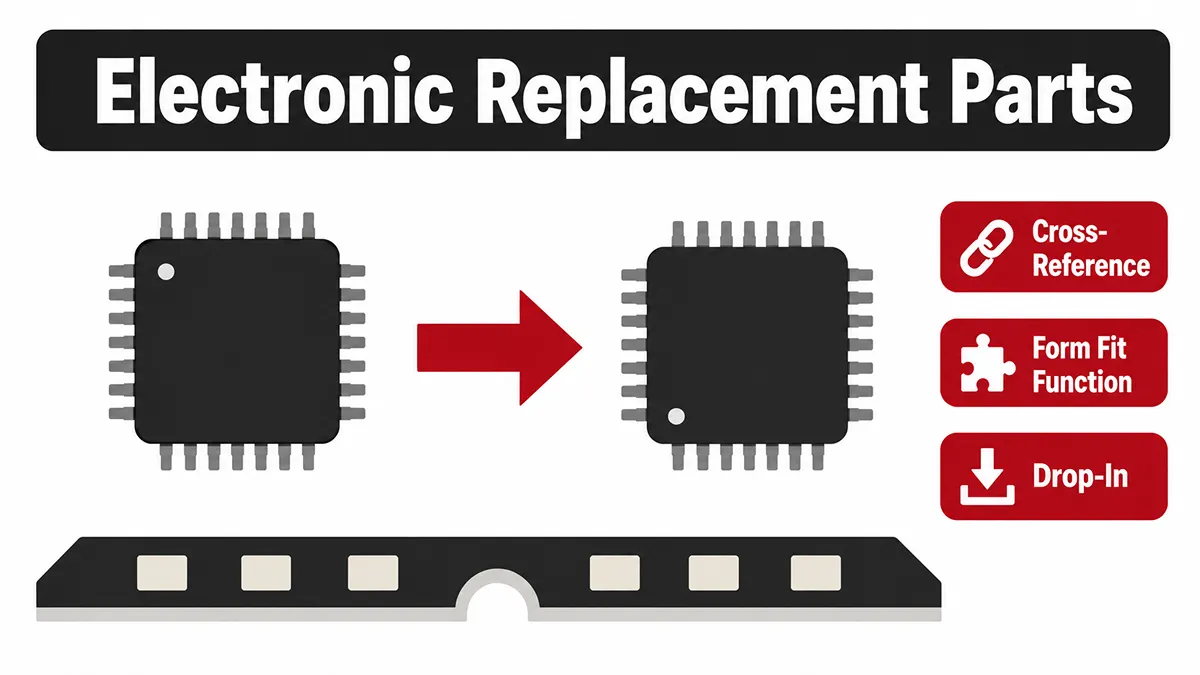
The industry data consistently shows that over 60% of component shortages are ultimately resolved through cross-referencing and qualifying alternative components, rather than resorting to a highly expensive printed circuit board (PCB) redesign.
This comprehensive guide explores how to identify electronic component equivalents using the industry-standard Form-Fit-Function framework, how to leverage dynamic cross-reference databases, and how to avoid the hidden technical pitfalls of swapping components.
Why Replacement Parts Are Needed
The need for sourcing electronic replacement parts in a manufacturing environment usually stems from one of three primary drivers:
- Component Obsolescence: The original manufacturer issues an EOL notice, permanently ceasing production. Knowing how to source and qualify obsolete electronic parts is a core competency for supply chain resilience, and cross-referencing is usually the first line of defense.
- Supply Chain Disruptions: The part is still in active production, but factory lead times have stretched to 40+ weeks, threatening to halt the assembly line.
- Cost Reduction Initiatives: A direct equivalent from a secondary or tertiary manufacturer may offer a more aggressive price point for high-volume manufacturing without sacrificing performance.
Drop-In and Functional Replacements
Before diving into datasheets, engineering teams must understand the distinct classifications of electronic replacement parts. Not all alternatives are created equal, and the type of replacement you choose dictates the amount of validation testing required.
| Replacement Category | Definition | PCB Redesign Required? | Validation Effort |
|---|---|---|---|
| Potential Drop-In Candidate | A candidate with a compatible footprint and pinout that may require no PCB change, subject to application-specific engineering qualification. | Not necessarily; confirm through qualification. | Medium to High, depending on circuit criticality, operating conditions, firmware, and compliance requirements. |
| Functional Equivalent | Performs the exact same role in the circuit but has a different package size or pinout. | Yes (Minor footprint/layout update). | Medium (Requires a new board spin and layout verification). |
| Similar/Downgraded Alternative | Similar function but may have lower tolerances, slower speeds, or different thermal ratings. | Potentially (Depending on system constraints). | High (Extensive system-level stress testing required). |
| Upgraded Alternative | Exceeds original specs (e.g., higher voltage rating, faster switching speed). | No | Medium (Must ensure higher specs don't cause secondary issues like EMI). |
The Form-Fit-Function Framework
Form-Fit-Function (FFF) is a practical framework for identifying and comparing potential replacement components. It asks three essential questions: Does the candidate have the required physical characteristics (Form)? Can it connect and install correctly in the existing design (Fit)? Can it perform the required job under the application’s defined conditions (Function)?
Form
- "Form" refers to the physical characteristics and the external geometry of the component. When evaluating form, engineers must verify:
- Package Type: Is the replacement the exact same package industry standard (e.g., SOIC-8, QFN-32, SOT-23)?
- Dimensions: Are the length, width, and height identical? A taller component might interfere with the mechanical enclosure or heat sink.
- Weight and Materials: For aerospace or portable applications, weight matters. Additionally, you must verify if the replacement is RoHS compliant or if it uses leaded solder, which affects manufacturing profiles.
Fit
"Fit" determines how the component physically interfaces with the PCB and the surrounding system. This goes beyond the general package type and dives into the microscopic details:
- Pinout Compatibility: Do all the pins align perfectly with the original footprint? Ground must map to ground, VCC to VCC, and I/O to I/O.
- Lead Pitch: The distance between the center of one pin and the center of the next must be mathematically identical to align with the PCB solder pads.
- Thermal Pads: Many power ICs have an exposed thermal pad on the bottom. Does the replacement have this pad, and is it identical in size to ensure proper solder wicking and heat dissipation?
Function
"Function" is the most complex pillar, assessing the electrical performance and software interaction of the component. Validation here includes:
- Electrical Parameters: Operating voltage ranges, current consumption, input/output impedance, and bandwidth.
- Tolerances: A 10k ohm resistor with a 1% tolerance cannot be replaced by a 10k ohm resistor with a 5% tolerance in a precision analog circuit.
- Firmware/Software Interaction: For microcontrollers or advanced digital sensors, does the replacement use the same instruction set, memory map, and I2C/SPI addresses? If not, a firmware rewrite is mandatory. We detail these exact firmware and timing validation steps in our analysis of pin-to-pin replacements for memory.
However, FFF is not the only approval criterion and should not be treated as proof that a candidate is a production-ready drop-in replacement. A component may match the footprint, pinout, and headline electrical ratings but still fail because of differences in thermal behavior, start-up timing, firmware compatibility, EMC/EMI performance, manufacturing requirements, reliability, or compliance status. Replacement parts must be evaluated in the actual circuit, production process, and product environment—not only in a datasheet comparison.
Before approving an alternative, teams also should assess: Cross-Reference Tools and Databases
For example, two DC/DC converters may share the same package, pinout, input-voltage range, and nominal output current. They may therefore appear to meet the FFF requirements at first review. Yet a different switching frequency, control-loop compensation method, soft-start profile, current-limit threshold, or thermal resistance can cause output ripple, instability, excess heat, or EMI failures on the existing PCB. The candidate may still be usable—but only after engineering validation confirms that the complete system remains within specification.
Finding Replacement Candidates
Finding an alternative starts by defining the original component’s non-negotiable requirements. These are the characteristics that the replacement must meet for the specific design, such as package limits, pinout, supply-voltage range, temperature grade, required interfaces, safety functions, or firmware dependencies.
Separate these requirements into two groups before searching:
- Must-have requirements: Parameters that cannot change without creating a PCB revision, firmware change, compliance risk, or unacceptable performance loss.
- Preferred requirements: Parameters that may differ if the design has adequate margin, such as a wider voltage range, a different packaging format, or a higher current rating.
- Supply-chain requirements: Lifecycle status, approved manufacturer status, production availability, traceability expectations, target price, and acceptable lead time.
With these requirements defined, work through sourcing channels in order of reliability:
- Original component manufacturer (OCM): Check the product page, PCNs, EOL notices, and official replacement recommendations. A manufacturer-recommended successor often includes migration guidance, making it the strongest starting point.
- Authorized distributors and parametric search tools: Filter by core specifications (for example, an LDO regulator search might include input-voltage range, 3.3 V output, output current, package, temperature grade, and protection features) to generate a cross-brand candidate list.
- Independent distributors and specialized sourcing networks: When no authorized-channel option exists, these networks can locate the original part or identify alternatives, while also addressing supply continuity and authenticity.
Regardless of the channel, treat every result as a candidate, not a confirmed replacement.
Need Help Finding Reliable Electronic Replacement Parts?
At VIGOR COMPONENTS, our global sourcing experts specialize in finding highly reliable, fully vetted alternatives for allocated, end-of-life (EOL), and hard-to-find electronic parts. With over 15 years of supply chain experience and strict quality inspection protocols, we help you keep your production lines moving without compromising on quality or board performance.
Upload Your BOM for a Free Cross-Reference Match →
Cross-Reference Tools and Databases
Cross-reference tools and parametric databases help engineering and procurement teams identify, organize, and compare potential replacement components. They are particularly valuable when a BOM includes obsolete, allocated, or single-source parts and a team must evaluate several manufacturers under time pressure.
Use these tools for three practical purposes:
- Part-number cross-reference: Find an original manufacturer’s recommended successor, a documented alternate, or a database-identified equivalent for a specific manufacturer part number.
- Parametric filtering: Build a preliminary list of components that meet measurable requirements, such as package family, pin count, operating-voltage range, output current, temperature grade, interface type, and lifecycle status.
- Documentation and lifecycle comparison: Compare datasheets, package drawings, PCNs, EOL notices, availability, and manufacturer status across multiple candidates.
| Tool Type | Best Use | Output to Expect |
|---|---|---|
| Original manufacturer resources | Finding official successors and migration guidance | Replacement part numbers, PCN/EOL notices, and application documentation |
| Distributor parametric search | Finding parts that satisfy defined measurable requirements | A broad preliminary candidate list |
| Cross-reference and BOM databases | Comparing candidate parts and monitoring lifecycle information | Visible parameter differences and prioritized alternatives |
The data may be incomplete, differently normalized across manufacturers, or unable to represent conditions that matter in a specific design. A parametric match can therefore identify a useful starting point while still missing an important limitation.
Before releasing a candidate for production, evaluate factors that structured search tools cannot fully confirm:
- Complete electrical behavior: Verify guaranteed minimum and maximum values, tolerances, timing, transient response, noise, protection thresholds, and derating—not only typical datasheet values.
- Thermal behavior in the actual product: Check power dissipation, junction-temperature margin, package thermal characteristics, PCB copper area, airflow, enclosure temperature, and maximum-load conditions.
- Firmware and system interfaces: Review boot behavior, register maps, default states, logic thresholds, driver support, bus timing, and manufacturer errata for software-visible components.
- Manufacturing compatibility: Confirm MSL, reflow limits, land-pattern requirements, exposed-pad geometry, packaging format, and assembly-process suitability.
- Compliance, quality, and supply continuity: Check qualification level, required certifications, RoHS/REACH documentation, lifecycle status, sourcing channels, traceability, and the replacement’s own NRND or EOL risk.
- Application-specific validation: Test representative samples on the target board under relevant operating conditions, including start-up, maximum load, temperature limits, fault response, and EMC/EMI requirements where applicable.
Use a clear internal status system to prevent an unverified candidate from being sourced as a production substitute:
- Candidate: Identified through a manufacturer, supplier, or search tool; no engineering review completed.
- Reviewed candidate: Documentation and core design requirements have been evaluated; further analysis or samples may be needed.
- Qualified replacement: Validated in the target application and formally released through the relevant Engineering Change Order (ECO) or approved-manufacturer process.
Cross-reference tools reduce the time needed to find and compare alternatives, but they do not replace engineering judgment or application-level qualification. Cross-reference search results must be verified against the data sheet before they can be considered suitable substitutes.
Common Replacement Mistakes
Transitioning to an alternative component is fraught with potential missteps. Avoiding these common errors will save your company from costly field failures and product recalls:
- Assuming "Pin-to-Pin" means "Plug-and-Play": Just because it fits on the board doesn't mean the internal logic or timing requirements are identical.
- Over-Specifying: Replacing an operational amplifier with a much "faster" equivalent (higher slew rate) seems like an upgrade, but it can induce high-frequency ringing, electromagnetic interference (EMI), and circuit instability.
- Ignoring the Supply Chain Status of the Replacement: There is no value in redesigning your board for a replacement part that is itself entering the NRND (Not Recommended for New Designs) phase. Always verify the lifecycle status of the new component.
- Skipping Physical Prototyping: Never push a datasheet-only replacement straight into high-volume manufacturing. Always order samples and run a pilot build to validate system-level performance.
Frequently Asked Questions
Does a pin-to-pin match guarantee a drop-in replacement?
No. A pin-to-pin match only satisfies the "Form" and "Fit" requirements. The component could have different timing logic, require different initialization firmware, or possess different thermal dissipation characteristics that cause the system to fail under heavy load.
Which specifications need margin beyond the original part?
Generally, voltage and current ratings can be equal to or higher than the original part (e.g., using a 50V capacitor to replace a 25V capacitor). However, parameters like timing tolerances, ESR (Equivalent Series Resistance) in capacitors, and switching frequencies must match the original design intent closely to avoid destabilizing the circuit.
Can a higher-rated component create new system risks?
Yes. Upgrading to a faster microprocessor or a higher-bandwidth operational amplifier can introduce unexpected high-frequency noise or electromagnetic interference (EMI). Additionally, higher-rated power components might have slower turn-on times or different gate charge requirements, impacting efficiency.
When should a replacement be validated with samples before production?
Always. Regardless of how perfectly the datasheets align, you must validate the replacement with physical samples on a prototype board. This is especially critical for analog components, power supplies, and high-speed digital transceivers, where minute physical variations drastically impact system behavior.
Who should approve an electronic replacement part before release?
A formal Engineering Change Order (ECO) should be utilized. The approval must be cross-functional, requiring sign-off from the hardware design engineer (for electrical validity), the software engineer (if firmware changes are needed), and the quality assurance manager (to verify compliance and regulatory standards).
References
- Defense Logistics Agency: MIL-PRF-38535 The foundational military specification establishing the general performance requirements for integrated circuits, often used as the baseline for Form, Fit, and Function (FFF) equivalency.
- Texas Instruments: Semiconductor and IC Package Thermal Metrics (PDF) A detailed engineering application report explaining the calculation and critical importance of Junction-to-Ambient Thermal Resistance (
 ) when qualifying replacement chips.
 - SmartSemi: Planning for Obsolescence Strategic analysis on proactive lifecycle management, emphasizing cross-referencing as the primary defense against unexpected component discontinuations.