
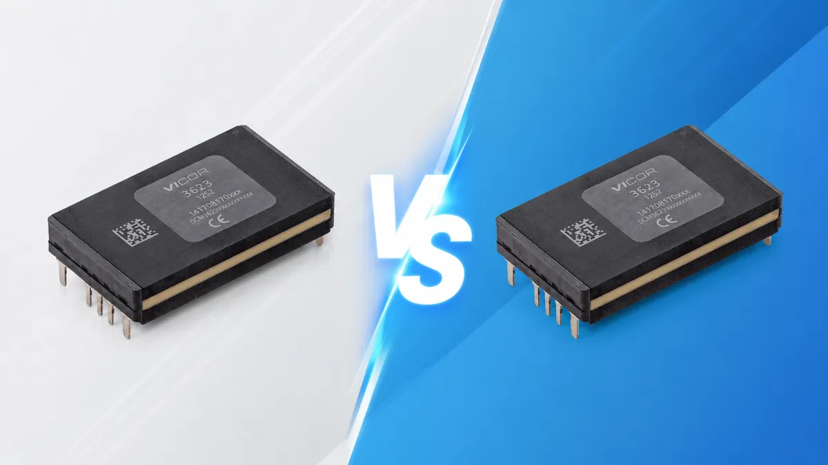
In modular power system design, the Vicor DCM3623 series is a benchmark for high power density, utilizing an advanced Zero-Voltage Switching (ZVS) topology and robust thermal packaging. However, due to similarities in part numbering, hardware engineers and strategic procurement managers frequently face challenges in distinguishing between specific configurations. This technical guide provides a rigorous comparative analysis of the DCM3623T75H26C2T00 and DCM3623T50M53C2T00 isolated, regulated DC-DC converters, clarifying their electrical parameters, architectural roles, and supply chain logistics.
Core Specs Side by Side
A direct lateral comparison of the publicly available engineering specifications reveals fundamental divergences in their voltage conversion matrices:
| Electrical / Physical Parameter | DCM3623T75H26C2T00 | DCM3623T50M53C2T00 |
|---|---|---|
| Package Standard | 3623 ChiP (38.72mm x 22.8mm x 7.21mm) | 3623 ChiP (38.72mm x 22.8mm x 7.21mm) |
| Mounting Configuration | Through-hole (Pins) | Through-hole (Pins) |
| Input Voltage Range | 36 Vdc to 75 Vdc (Wide Range) | 16 Vdc to 50 Vdc (Wide Range) |
| Nominal Input Voltage | 48 Vdc | 24 Vdc / 28 Vdc |
| Rated Output Voltage | 24 Vdc (Trim Range: 12.0 V to 26.4 V) | 48 Vdc (Trim Range: 24.0 V to 52.8 V) |
| Maximum Output Power | 320 W | 320 W |
| Max Continuous Output Current | 13.33 A | 6.67 A |
| Peak Efficiency | Up to 93.6% | Up to 92.5% |
| Temperature Grade | T-Grade (-40°C to 125°C Internal Junction) | T-Grade (-40°C to 125°C Internal Junction) |
While both modules share identical physical dimensions (3623 ChiP) and a maximum power ceiling of 320W, they implement entirely inverted voltage transformation profiles. The T75H26 is engineered for step-down power distribution, whereas the T50M53 focuses on boosting lower intermediate bus voltages to higher distribution rails. Internal power MOSFET voltage ratings and transformer turns ratios differ substantially between the two.
48V vs 24V Output Bus Architectures
The selection of a Distributed Power Architecture (DPA) intermediate rail directly dictates the system's thermal overhead and copper distribution costs:
- 24V Output Bus (DCM3623T75H26C2T00): A 24V rail serves as a legacy standard across industrial automation, PLC racks, and traditional security surveillance ecosystems. It benefits from a mature downstream Point-of-Load (PoL) buck regulator market. However, at 320W, a 24V bus generates a high continuous current of 13.33A. This demands thick PCB copper planes (2 oz or 3 oz) and wider trace layouts to limit
 distribution losses and local voltage drops.
 - 48V Output Bus (DCM3623T50M53C2T00): A 48V rail aligns with modern high-performance data centers, telecommunication basestations, and advanced 48V mild-hybrid vehicle (MHEV) architectures. Elevating the intermediate rail to 48V cuts the continuous current precisely in half to 6.67A for the same 320W power delivery. Because conduction losses scale quadratically with current (
 ), a 48V architecture yields up to a 75% reduction in distribution line losses, facilitating minimized heatsink volumes and denser PCB layouts.
Input Voltage Range Differences
The input voltage windows of these DC-DC converters function as critical barriers protecting downstream electronics from unstable primary power supplies. Engineers must match these windows to worst-case operating transient profiles:
The DCM3623T75H26C2T00 operates over a 36V to 75V standard telecom input window. Optimized for nominal 48V battery backup arrays and centralized DC buses, its internal Under-Voltage Lockout (UVLO) activates near 36V to prevent deep battery discharge, while its upper limit accommodates transient line surges up to 75V without stress.
Conversely, the DCM3623T50M53C2T00 utilizes a 16V to 50V input window, optimized for nominal 24V or 28V power systems. The low 16V minimum is highly valuable for vehicular or industrial cranking conditions, ensuring the module continues to deliver a stable 48V output even during severe primary bus sags. However, its upper limit is constrained to 50V; any voltage spike exceeding this threshold triggers Over-Voltage Lockout (OVLO) to protect the internal ZVS bridge.
Why These Two Modules Cannot Be Swapped
Cross-substitution of these two part numbers during component shortages presents severe, destructive risks to hardware assemblies:
First, their non-overlapping voltage parameters prevent functional operation. Deploying the T50M53 (16-50V input) into a standard 48V telecom bus running at 54V will immediately trigger the module's OVLO mechanism or cause overvoltage breakdown of the primary-side switchgear. Conversely, placing the T75H26 (36-75V input) onto a nominal 24V industrial bus ensures the device remains permanently disabled, as the bus voltage sits well below its 36V turn-on threshold.
Second, the output voltage mismatch represents a catastrophic hazard. Directing a 48V output from a misplaced T50M53 into a downstream power distribution network designed exclusively for 24V components will instantly exceed the dielectric breakdowns of MLCC filtering capacitors, PoL regulators, and peripheral ICs, leading to immediate circuit destruction.
Thermal Management and Power Density
Achieving high power density within the 3623 ChiP package depends heavily on dual-sided thermal dissipation through high-conductivity encapsulating resin. However, the distinct current profiles of these modules necessitate different board-level thermal layouts:
The DCM3623T75H26C2T00 generates significant conduction losses at its output pins due to the 13.33A rating. Board designers must prioritize conduction cooling through the PCB pins by placing large, unmasked copper pours connected to internal ground planes via a dense array of thermal vias.
The DCM3623T50M53C2T00 exhibits lower output pin conduction losses due to its 6.67A maximum current. However, its primary thermal stress occurs when operating at the low-end input limit (16V) under full load, where primary-side switching currents peak, maximizing ZVS FET conduction losses and transformer copper losses. Designers must consult the manufacturer's thermal derating curves and implement forced airflow or top-side heatsinks if operating at elevated ambient temperatures or low input bounds.
Sourcing Reliable Components via Vigorcomp
Navigating the volatile global electronic supply chain requires a sourcing partner capable of validating technical parameters alongside logistical delivery.
As a leading global independent electronic components distributor, Vigor Components secures robust supply pathways for high-demand power modules like the Vicor DCM3623 series.
Understanding that structural package compatibility does not equal electrical interchangeability, Vigorcomp protects your production lines from costly procurement errors. Our rigorous quality assurance protocol includes exhaustive component inspections—ranging from microscopic package microscopy to lead oxidation screening and basic parametric testing—ensuring zero counterfeit or out-of-spec parts reach assembly. Whether mitigating long factory lead times or resolving unexpected end-of-life (EOL) component crunches, Vigorcomp delivers verified, genuine components backed by engineering expertise.
Frequently Asked Questions
Why do these two DCM3623 modules share identical physical dimensions?
They are constructed on Vicor’s standardized 3623 ChiP (Converter housed in Package) mechanical platform. Standardizing the external footprint allows hardware teams to reuse mechanical housing and manufacturing fixtures across different product tiers, even though the internal transformers, control IC programming, and FET silicon ratings are completely distinct.
If the DCM3623T75H26C2T00 is out of stock, can I use the T50M53 and step down its 48V output to 24V?
While technically feasible by adding a secondary buck stage, this workaround introduces substantial BOM costs, compromises overall system efficiency, and expands the physical board footprint. The recommended approach is to contact Vigor Components to identify an electrically compatible drop-in alternative, such as an alternative temperature grade or minor packaging suffix variant.
What parameters define the T-Grade temperature specification?
The T-Grade designation certifies an internal operating junction temperature range from -40°C to 125°C. This profile is well-suited for industrial control, commercial infrastructure, and standard outdoor telecommunications equipment. For aerospace or extreme defense environments requiring operation down to -55°C, an M-Grade variant is mandatory. Contact Vigorcomp to review availability for extended temperature grade modules.