
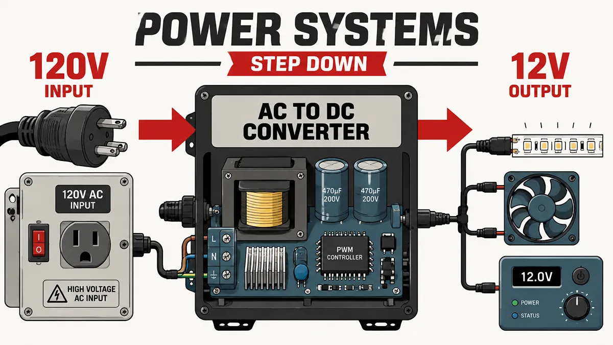
North American mains power is typically 120V AC at 60Hz. A low-voltage device must not be connected directly to a 120V AC outlet unless it is specifically rated for that input.
For procurement and system integration, converting 120V to 12V is not a single product decision. The correct solution depends on whether the load requires 12V AC or 12V DC, its continuous and peak power demand, the installation environment, and the applicable safety and compliance requirements.
This guide focuses on selecting and sourcing suitable 120V-to-12V power solutions for commercial, industrial, outdoor, mobile, and electronics applications.
Confirm Whether Your Load Requires 12V AC or 12V DC
“120V to 12V” does not identify the required output type. Before selecting a power source, verify the load label or datasheet for its input voltage, current type, frequency, polarity, current requirement, maximum power, and any control or dimming requirements.
| Load Input Marking | Typical Solution | What to Verify |
|---|---|---|
| 12V AC, 50/60Hz | 120V AC to 12V AC Step-Down Transformer | VA rating, output tolerance, cable length, and fixture compatibility |
| 12V DC with polarity marking | Isolated 120V AC to 12V DC Power Supply | Output-voltage tolerance, polarity, continuous current, peak current, and connector type |
| 12–24V AC/DC | Power Source Within the Stated Operating Range | Input range, frequency, power rating, and dimming/control compatibility |
| Constant-current LED rating, such as 350mA or 700mA | Constant-Current LED Driver | LED forward-voltage range, output current, dimming method, and thermal conditions |
A 12V AC transformer lowers the mains voltage while retaining an AC output. It is commonly used where the load is specifically designed for low-voltage AC, including some halogen landscape-lighting systems.
Many LED products, security cameras, control boards, and telecommunications devices use 12V DC. However, product category alone is not enough to confirm compatibility. Some fixtures and devices accept 12V AC, 12V DC, or both; the product documentation remains the final authority.
Do not connect a 12V AC source to a load marked only for 12V DC unless the manufacturer explicitly states AC-input compatibility. The result depends on the device input circuitry and may range from incorrect operation to component damage.
Choose the Right 120V-to-12V Solution
The output type determines the fundamental product category. For DC-powered applications, understanding the major types of DC converters can help engineers distinguish between step-down, step-up, buck-boost, and isolated conversion approaches.
| Requirement | Recommended Product Category | Typical Procurement Focus |
|---|---|---|
| 120V AC to 12V AC | Step-Down Transformer | VA capacity, 50/60Hz compatibility, thermal protection, enclosure, and low-voltage wiring |
| 120V AC to Regulated 12V DC | Isolated AC-DC Power Supply | Output regulation, ripple specification, protections, approvals, derating, and terminals/connectors |
| 120V AC to 12V DC for Outdoor Use | Outdoor-Rated AC-DC Power Supply or LED Driver | Input/output specification, enclosure rating, cable glands, sealing, and operating-temperature range |
| 120V AC to 12V for Industrial Panel Use | DIN-Rail AC-DC Power Supply | Mounting format, EMC, protection functions, status indication, redundancy options, and derating |
| Board-Level 12V DC Rail | Certified AC-DC Module or a Qualified Custom Power Design | Isolation rating, PCB safety design, agency approvals, BOM availability, lifecycle status, and documentation |
For a standard 12V DC power supply, evaluate output-voltage tolerance, ripple and noise, load regulation, transient response, hold-up time where relevant, and protection behavior. These specifications must be matched to the load’s actual operating limits rather than to a generic 12V threshold.
Calculate Power, Current, Inrush, and Derating Margin
The basic output-power relationship is:
P=V×I
For example, a 12V load drawing 10A requires 120W of continuous output power:
12V×10A=120W
Calculate the total continuous load first. Then assess peak current, motor starting current, capacitive inrush, LED-driver inrush, simultaneous-load conditions, ambient temperature, airflow, mounting orientation, and altitude when applicable.
Using approximately 80% of rated output can be a practical initial capacity margin. A 100W continuous load, for example, suggests beginning the selection process with a 125W or higher supply:
100W/0.80=125W
This is not a universal industry requirement. Final sizing should follow the manufacturer’s output-derating curve and installation conditions. A supply that is appropriately rated at room temperature may require additional capacity in a sealed enclosure, at elevated ambient temperature, or where the load has significant repetitive peaks.
Match the Product to the Environment
Electrical ratings do not by themselves ensure suitability. Environmental and mechanical conditions can determine the correct product format, enclosure, connector, and service life.
| Application | Typical Solution | Key Selection Criteria |
|---|---|---|
| RV Interior Lighting and 12V Accessories | Isolated 120V AC to 12V DC Supply | Vibration, shock, confined-space heat, terminal retention, and surge tolerance |
| Low-Voltage Halogen Landscape Lighting | 120V AC to 12V AC Transformer | Fixture compatibility, VA rating, cable voltage drop, and installation location |
| Outdoor LED Landscape Lighting | 12V AC Transformer, 12V DC Supply, or Compatible LED Driver | Fixture input type, dimming compatibility, connector sealing, and enclosure rating |
| Security Cameras and Access-Control Devices | 120V AC to 12V DC Supply | Peak current, cable voltage drop, output regulation, backup-power design, and temperature range |
| Factory-Floor Controls and Actuators | Industrial AC-DC Power Supply | EMC requirements, fault protection, thermal derating, mounting, and maintenance access |
For outdoor installations, select the enclosure rating based on actual exposure conditions. IP55, IP65, IP66, IP67, or an applicable NEMA rating may be appropriate depending on dust, rainfall, spray, washdown, or temporary immersion risk. IP67 should not be treated as a default requirement for all outdoor applications.
For RV and mobile systems, check vibration, shock, connector retention, operating temperature, and ventilation. Potting may be suitable for some products, but should be specified only when the mechanical and thermal requirements justify it.
Verify Safety, Compliance, and Procurement Requirements
For a finished 120V-to-12V power product, procurement review should include more than output power and price.
- Input rating: Confirm the 120V AC input range, frequency rating, plug or terminal configuration, and protective-earth requirements.
- Output specification: Verify nominal voltage, tolerance, continuous current, peak-load capability, ripple/noise, regulation, and start-up behavior.
- Protection functions: Check short-circuit, overcurrent, overvoltage, and overtemperature protection, including whether the unit auto-recovers or latches off.
- Safety approvals: Match approvals to the target market and product category, such as UL, cUL, CSA, CE, or other required certifications.
- EMC requirements: Confirm whether the product is suitable for the installation’s conducted and radiated-emissions environment.
- Environmental limits: Review operating temperature, humidity, altitude, vibration, ingress protection, and enclosure requirements.
- Derating data: Request the manufacturer’s derating curve and confirm capacity at the actual ambient temperature and installation orientation.
- Installation details: Verify wire gauge, terminal torque, connector type, output polarity, grounding, fusing, clearance for ventilation, and cable voltage drop.
- Supply-chain controls: Confirm approved manufacturer status, traceability, lifecycle status, lead time, alternate sources, documentation availability, and warranty terms.
For board-level isolated AC-DC modules or custom power designs, PCB insulation coordination also requires engineering review. Creepage distance and clearance depend on factors such as working voltage, insulation type, pollution degree, material group, altitude, transient-overvoltage conditions, and required insulation classification. They cannot be set solely from a “120V-to-12V” label.
Source Power Solutions for Your Application
A suitable 120V-to-12V solution begins with a complete set of requirements: input type, required AC or DC output, continuous and peak current, operating environment, mechanical form factor, safety approvals, and expected product lifecycle. Once the required output is defined, understanding the underlying conversion technology can help engineers evaluate the right power architecture. Learn more in our guide to what a DC converter is.
For established applications, a qualified transformer, AC-DC power supply, DIN-rail unit, or LED driver may be the fastest path. For board-level products or long-lifecycle equipment, procurement teams should also evaluate approved components, second sources, PCN/EOL exposure, documentation, and technical support before releasing a BOM.
If your system already runs on a 24V or 48V DC bus rather than 120V AC mains, refer to our guides on 24V to 12V conversion and 48V to 12V conversion for point-of-load design considerations.
VIGOR COMPONENTS supports sourcing for power modules, transformers, rectifiers, power-management ICs, MOSFETs, capacitors, inductors, optocouplers, connectors, and related electronic components. Submit your BOM or technical requirements for sourcing support and availability review.
Frequently Asked Questions
Can I use a 12V DC power supply for a 12V AC halogen system?
Only if the lamp or fixture manufacturer explicitly states that 12V DC input is supported. A compatible AC transformer should power a product labelled only for 12V AC.
Is 12V AC the same as 12V DC?
No. The voltage type, waveform, polarity, and RMS/peak behavior differ. Select the power source according to the load label or datasheet.
How many amps do I need for a 12V, 100W load?
The nominal continuous current is approximately 8.33A: 100W/12V=8.33. Also account for inrush current, peak loading, derating, cable voltage drop, and the manufacturer’s recommended supply margin.
Does every outdoor 12V power supply need IP67?
No. The required protection level depends on the actual installation environment. Select the enclosure rating based on the expected dust and water exposure and the applicable installation requirements.