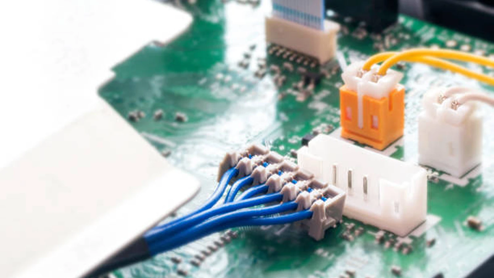
System assembly constraints, vibration limits, and field maintenance workflows dictate whether an engineer should specify a wire-to-board (WTB) or wire-to-wire (WTW) connector. A wire-to-board connector brings discrete wires or ribbon cables directly onto a printed circuit board (PCB), serving as the final entry point for power and signals. A wire-to-wire connector joins two cable harnesses together without touching a PCB, creating an in-line splice, a harness extension, or a bulkhead disconnect point across an enclosure panel.
In industrial equipment, engineers rarely treat these two configurations as mutually exclusive. Instead, a well-designed wiring harness routes power and sensor lines from a PCB header (wire-to-board) through an enclosure wall or intermediate service loop (wire-to-wire) so technicians can replace damaged field cables without opening the main control board housing.
Quick Comparison Between Wire-to-Board and Wire-to-Wire Connectors
While both connector categories rely on similar contact physics and plastic insulating housings, their mechanical mounting, stress points, and maintenance workflows differ significantly.
| Comparison Dimension | Wire-to-Board (WTB) Connectors | Wire-to-Wire (WTW) Connectors |
|---|---|---|
| Primary Interface | Discrete wires or cable harness to a PCB | Cable harness to another cable harness |
| Mating Halves | Soldered PCB header + wire-side receptacle housing | Wire-side plug housing + wire-side receptacle housing |
| Mounting Style | Through-hole (THT) or surface mount (SMT) on PCB | Free-hanging (in-line) or panel mount (bulkhead) |
| Mechanical Stress Point | PCB solder joints, copper pads, and retention pegs | Housing latches, panel mounting ears, and cable strain reliefs |
| Field Serviceability | Requires enclosure access to unplug directly from the board | Allows quick cable disconnection outside the board area |
| Typical Industrial Use | Internal PCB power delivery, sensor I/O headers, motor drive boards | Field sensor extensions, cabinet wall pass-throughs, robotic arm joints |
How Wire-to-Board Connectors Work on Printed Circuit Boards
A wire-to-board interconnect bridges flexible wiring and rigid board traces. When evaluating whether to link internal subassemblies via cables or rigid headers, engineers often first weigh board-to-board vs. wire-to-board connectors to balance packaging space against routing flexibility. Once a cabled architecture is chosen, the WTB interface becomes the critical mechanical boundary on the PCB.
Board-Side Headers and Wire-Side Receptacle Housings
A standard two-piece WTB system consists of a rigid header mounted to the circuit board and a mating receptacle housing attached to the wire harness:
- Board-Side Header: Typically houses male metal pins (posts) surrounded—either partially or fully—by a plastic shroud. Shrouded (box) headers guide the mating plug into alignment and prevent technicians from bending exposed pins during blind mating.
- Wire-Side Receptacle: Consists of an empty plastic housing and separate female metal crimp sockets. During harness fabrication, operators strip the wire insulation, crimp the metal socket onto the conductor and insulation barrel, and insert the terminated wire into the plastic housing cavity until an internal lance clicks into place.
Through-Hole vs Surface Mount PCB Stress Considerations
Because every mating and unmating cycle applies push-and-pull forces directly to the circuit board, choosing the right PCB termination method is essential for long-term reliability:
- Through-Hole Technology (THT): Header pins pass entirely through plated holes in the PCB and are soldered on the opposite side. THT headers provide high mechanical pull-out strength, making them the preferred choice for larger wire gauges (such as 18 AWG to 14 AWG), high-current power inputs, and connectors that technicians unplug during routine maintenance.
- Surface Mount Technology (SMT): Header leads rest flat on surface copper pads and undergo automated reflow soldering. SMT headers save board space and simplify double-sided PCB assembly for fine-pitch signal interfaces (such as 1.0 mm to 2.0 mm pitch). However, pulling sideways on an SMT connector can peel copper pads right off the laminate. For industrial SMT designs, always specify headers with metal solder tabs (hold-down nails) or plastic alignment pegs to anchor the housing mechanically.
How Wire-to-Wire Connectors Join Cable Assemblies
When a wiring path is too long for a single continuous run, passes through a metal bulkhead, or connects a moving subassembly that wears out over time, wire-to-wire connectors provide a modular break point.
Free-Hanging In-Line Connections vs Panel Mount Housings
Wire-to-wire housings are divided into two mechanical mounting categories depending on how the harness is supported:
- Free-Hanging (In-Line) Connectors: Both the plug and receptacle housings float freely along the cable run, held together solely by their mating latch. Free-hanging WTW connectors work well inside enclosed cable trays, wiring ducts, or lightweight assemblies where cable ties secure the harness near the connector body.
- Panel Mount Connectors: One half of the connector features integrated mounting ears, snap-in clips, or threaded flanges that lock into a cutout on an equipment chassis or control cabinet wall. Panel-mount WTW designs isolate internal wiring from external field cabling and absorb mechanical tension so pulling on an external cord never transfers strain to internal electronics. In heavy-duty machinery, these pass-through interfaces often rely on rugged rectangular connector housings to organize multi-pole power and signal lines in a single panel cutout.
Male and Female Terminal Mating Rules
A frequent source of confusion during BOM preparation is how manufacturers label "plug" and "receptacle" versus "male" and "female" in wire-to-wire systems. In many connector families—such as the Molex Mini-Fit Jr. or Micro-Fit 3.0 series—the plastic plug housing with the exterior locking ramp actually holds female crimp sockets, while the mating receptacle housing holds male crimp pins, or vice versa depending on the specific product line.
To avoid ordering mismatched parts, always verify gender based on the metal contact (pin vs. socket) rather than the plastic shell silhouette. As a standard safety practice in industrial wiring, assign female sockets (recessed contacts) to the energized power-supply side of a WTW disconnect so exposed metal pins cannot accidentally short against a grounded metal chassis when unplugged.
Key Engineering Parameters for Connector Datasheet Selection
Moving from a conceptual wiring diagram to an actual manufacturer part number requires checking three core datasheet parameters that govern electrical stability and mechanical retention.
Crimp Termination vs Insulation Displacement Connectors
Both WTB and WTW connectors primarily use either crimp termination or insulation displacement termination:
- Crimp Termination: Wires are stripped and mechanically compressed into individual metal terminals before insertion into the housing. Crimping accommodates a wide range of wire gauges, supports high current ratings, and delivers superior gas-tight resistance against vibration and thermal cycling.
- Insulation Displacement Connectors (IDC): Sharp metal blades inside the connector slice through the wire insulation during a single press operation, eliminating the wire-stripping step. While IDC headers and plugs speed up mass production for low-current ribbon cables and signal harnesses, they generally handle lower currents and offer less vibration resistance than discrete crimped terminals.
Pitch Size Wire Gauge and Current Derating
Pitch measures the center-to-center distance between adjacent pins (commonly ranging from 1.0 mm and 1.25 mm for compact signals up to 3.0 mm, 4.2 mm, and 6.35 mm for power). While a larger pitch generally allows thicker wires and higher voltage creepage distances, engineers and buyers must read datasheet current ratings carefully.
A headline specification such as "Up to 8.5 A" or "Up to 13 A per contact" almost always represents the theoretical maximum tested on a 2-circuit housing using the largest permissible wire gauge in free air. When a 12-circuit or 24-circuit connector is fully populated and carrying current simultaneously, mutual heating reduces the safe capacity of each pin. Always consult the manufacturer's current derating curves in the datasheet to verify allowable amperage based on ambient temperature, circuit count, and exact AWG wire size.
Positive Locking Latches and Terminal Position Assurance
In static consumer devices, a simple friction lock (detent) between the mating plastic walls is sufficient to keep a WTB header seated. In industrial machinery, continuous vibration from motors and actuators can gradually walk a friction-locked connector apart, causing intermittent open circuits.
For industrial WTB and WTW interfaces, specify housings with a positive locking latch that produces an audible click and requires deliberate thumb pressure to release. For mission-critical harnesses, add a Terminal Position Assurance (TPA) retainer—a secondary plastic clip inserted into the back of the housing that physically blocks crimped terminals from backing out if an operator fails to seat a contact fully during harness assembly.
Comparing Wire-to-Board vs Wire-to-Wire Connectors for Industrial Automation
When engineers compare wire-to-board vs wire-to-wire connectors for industrial automation, the most reliable systems combine both architectures strategically to minimize downtime and protect sensitive boards.
Inside the Control Cabinet vs Field Wiring Disconnects
Inside an industrial enclosure housing a programmable logic controller (PLC), motor drives, and power distribution boards, internal interconnections prioritize density and assembly speed. While modular rack systems often rely on board-edge or backplane interfaces such as DIN 41612 connectors to slot daughterboards into a chassis, peripheral sensor boards, cooling fans, and auxiliary DC power modules typically connect via wire-to-board headers. Direct WTB connections eliminate extra cable joints inside the cabinet where space is tight and cables remain undisturbed.
Once wiring leaves the protected cabinet interior to reach limit switches, optical sensors, or flexing robotic arms, wire-to-wire connectors become essential. Placing a panel-mount or in-line WTW connector between the internal WTB harness and the external field cable creates a clean service boundary:
- Rapid Field Replacement: When a cable on a moving gantry or conveyor is crushed or abraded, maintenance technicians can unclip the external WTW segment and snap in a spare harness in seconds without opening the control cabinet or touching the PCB.
- Modular Pre-Testing: Equipment builders can assemble, wire, and test the main control box using internal WTB harnesses at one workstation while fabricating external WTW field harnesses separately, joining them only during final machine integration.
- PCB Strain Isolation: Heavy industrial multi-conductor cables exert significant weight and bending torque. Anchoring that cable at a bulkhead WTW receptacle prevents mechanical pull from reaching delicate PCB solder joints.
Vibration Resistance IP Sealing and Polarization
Industrial automation environments introduce hazards rarely seen in office electronics:
- Polarization and Keying: Both WTB and WTW housings used on factory floors should feature asymmetric chamfers, ribs, or keying slots so a plug cannot be forced in upside-down. When multiple identical-pin-count headers sit side by side on a control board, selecting housings with different color codes or mechanical keying options prevents cross-plugging during field servicing.
- Environmental Sealing (IP67/IP68): Standard open-pin PCB headers cannot easily be sealed against washdown water, cutting fluids, or conductive dust. When a sensor cable enters a wet or dusty zone, designers use unsealed WTB connectors inside the IP-rated enclosure and transition to environmentally sealed WTW connectors (equipped with silicone wire seals and perimeter interface gaskets) for all external cable-to-cable junctions.
Popular Connector Series Supporting Both Configurations
One of the most effective ways to simplify harness manufacturing and inventory management is to select a unified connector family that offers both wire-to-board headers and wire-to-wire plugs within the same series.
When a connector family supports both configurations, the wire-side receptacle housing and female crimp terminals remain identical whether the harness plugs into a PCB header or mates with a free-hanging wire plug. This commonality reduces the number of unique crimp terminals, wire gauges, and expensive crimping applicator dies required on the production floor.
| Connector Series | Configuration Support | Pitch (mm) | Nominal Max Current (Condition Dependent) | Primary Industrial & Board Applications |
|---|---|---|---|---|
| JST PH Series | WTB Primarily | 2.0 mm | Up to 2.0 A (with 24 AWG wire) | Compact internal board signals, battery packs, low-power sensors |
| JST XH Series | WTB Primarily | 2.5 mm | Up to 3.0 A (with 22 AWG wire) | Auxiliary PCB power, display modules, internal control boards |
| Molex Micro-Fit 3.0 | Both WTB & WTW | 3.0 mm | Up to 8.5 A (2-circuit max with 18 AWG) | Dense industrial power/signal, PLC peripherals, TPA-supported harnesses |
| Molex Mini-Fit Jr. | Both WTB & WTW | 4.2 mm | Up to 9.0 A–13.0 A (depends on terminal metal & AWG) | Industrial power distribution, motor drives, panel-mount cable breaks |
| TE Economy Power (EP) | WTB & WTW Variants | 3.96 mm / 5.08 mm | Up to 7.5 A–10.5 A (series & AWG dependent) | HVAC controls, industrial appliances, power supply output harnesses |
| TE Dynamic Series (e.g., D-3000) | Both WTB & WTW | 3.81 mm / 5.08 mm | Up to 15.0 A (contact & housing dependent) | Factory automation, servo drives, high-vibration control cabinets |
Engineering Note: All current ratings listed above represent nominal maximum limits under specific low-circuit-count test conditions and maximum allowable wire gauges. Always verify exact part numbers, contact plating (tin vs. gold), and multi-circuit thermal derating charts in the official Molex, JST, or TE Connectivity datasheets before finalizing your design.
How to Choose the Right Connector Configuration for Your BOM
When preparing an electronic bill of materials (BOM) for a new industrial controller or wiring harness, follow this four-step verification checklist to avoid assembly bottlenecks and purchasing errors:
- Map the Maintenance Boundary: Use wire-to-board connectors for permanent or semi-permanent internal board links, and insert wire-to-wire disconnects at enclosure walls or high-wear motion zones so field technicians never need to pull on PCB headers.
- Audit Complete Mating Part Numbers: A single WTB or WTW connection rarely consists of one part number. For a standard crimped WTW link, your BOM must separately list the plug housing, receptacle housing, male crimp terminals, female crimp terminals, and any optional TPA clips or cable seals. Missing the crimp terminal line item is one of the most common causes of prototype build delays.
- Match Insulation Diameter as Well as AWG: Crimp terminals are specified not only by wire conductor gauge (such as 20–24 AWG) but also by the outer insulation diameter (OD) in millimeters. Industrial wires with thick UL-rated insulation may not fit into standard-profile crimp barrels or housing cavities even if the copper AWG matches.
- Never Cross-Mate Different Brands Without Verification: Even if two connectors share a 2.5 mm, 3.0 mm, or 4.2 mm pitch and look similar in photos, housing latch geometries, polarization ribs, and contact wipe lengths vary across manufacturers. Treat alternative series as complete mating-pair replacements rather than mixing a Brand A plug with a Brand B header unless explicitly validated.
Frequently Asked Questions
Can you use the same crimp terminals for both wire-to-board and wire-to-wire connectors?
Within a unified connector family—such as the Molex Micro-Fit 3.0 or Mini-Fit Jr. series—the female receptacle housing and its female crimp terminals are often identical for both wire-to-board and wire-to-wire connections. However, the mating half differs: a wire-to-board setup pairs that receptacle with a soldered PCB header, whereas a wire-to-wire setup pairs it with a free-hanging or panel-mount plug housing that requires separate male crimp terminals. Always check the manufacturer's mating matrix for your exact housing part number.
When should you combine wire-to-board and wire-to-wire connectors in one system?
Combining both types is standard practice whenever an external sensor, actuator, or power cable connects to an enclosed PCB. The cable harness plugs into the PCB via a wire-to-board connector, runs to the enclosure wall where it transitions through a panel-mount wire-to-wire connector, and continues into the field. This hybrid layout protects the PCB from mechanical pull forces and allows damaged external cables to be swapped without opening the electronics housing.
Which connector type handles high vibration better in industrial machinery?
Vibration reliability depends more on the locking mechanism and strain relief than on whether the connector is wire-to-board or wire-to-wire. However, heavy cables vibrating directly on a PCB-mounted WTB header—especially a surface-mount (SMT) header—can fatigue solder joints over time. In high-vibration machinery, securing the cable with a panel-mount WTW connector featuring a positive latch and Terminal Position Assurance (TPA) clips before routing lighter, strain-relieved wires to a through-hole WTB header offers the highest mechanical reliability.
Streamline Your Connector & Harness Component Sourcing
Sourcing complete connector systems requires matching housings, PCB headers, crimp terminals, and TPA accessories without part-number gaps. Whether you are building prototypes or managing production lead times for Molex, TE Connectivity, JST, or alternative interconnect series, Vigor Components helps engineering and procurement teams verify and source complete BOM line items.
Submit Your BOM or RFQ