
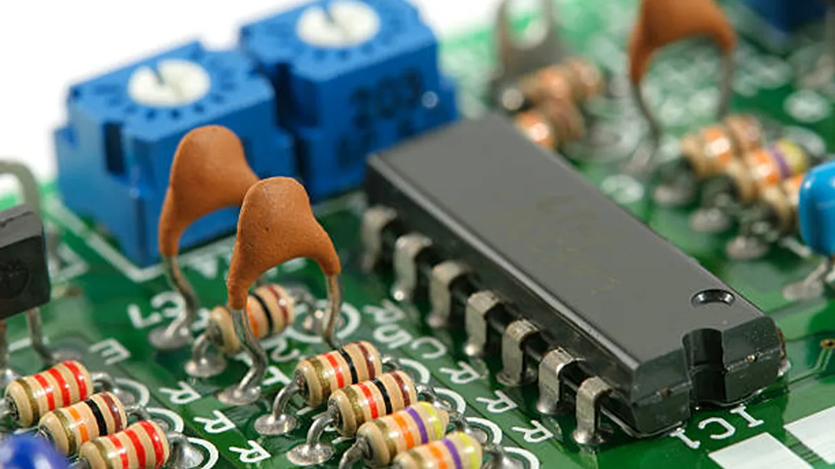
A PCB mount power supply sits directly on your board, converting and isolating power where the load actually lives. But matching one to your design is not a datasheet exercise. The specs that look fine on paper can fail in production when transient loads, thermal limits, and sourcing realities collide. This guide walks through the decisions that determine whether your chosen module works on the first board spin or causes weeks of rework.
What Makes a Power Supply "PCB Mount"?
A PCB mount power supply is a converter module soldered directly onto the host PCB, delivering regulated DC to nearby loads. Unlike enclosed or open-frame supplies that mount on a chassis, these modules provide only the conversion and isolation stage. The filtering, protection, and bulk capacitance stay on your board, giving you control over the complete power architecture.
This distinction matters because it determines what you are responsible for. The module handles isolation, regulation, and sometimes EMI filtering. Everything else, from input TVS diodes to output bulk capacitors, is your design call. For a deeper comparison of board mount module types, form factors, and sourcing strategy, see What Board Mount Module Specs Don't Tell You.
How Do You Match Output Specs to Your Load?
Output voltage is the first decision, and it has three layers: fixed, trimmable, or programmable.
Fixed output modules lock you into one rail. The Cosel MGFW152405-R delivers a fixed ±5V dual output at 1.5A per rail (15W total), which is ideal when your load rails are well defined and unlikely to change.
Trimmable modules give you an adjustment range. The Vicor V24C24T50BN supports output voltage trim from 10% to 110% of nominal via its TRM pin, letting a single 24V/50W module serve loads needing anything from 2.4V to 26.4V. This flexibility is valuable during prototyping when the optimal output voltage may still be in flux.
Programmable outputs via PMBus or I2C allow dynamic voltage scaling in server and FPGA applications where the load demands real-time adjustment.
| Output Type | Adjustment | Use Case | Example |
|---|---|---|---|
| Fixed | None (rated voltage only) | Standard rails, simple designs | Cosel MGFW152405-R (±5V) |
| Trimmable | 10% to 110% of nominal | Margin tuning, prototyping | Vicor V24C24T50BN |
| Programmable | Full digital control | Dynamic voltage scaling, telemetry | Vicor DCM with digital interface |
Current rating needs headroom, not just matching. If your load draws 2A steady-state but spikes to 3A during startup or transient events, a module rated for exactly 2A will trigger current limit and potentially drop the rail. The V24C24T50BN is rated for 2.08A at 24V (50W), which means it handles a 2A nominal load with roughly 4% margin. For tighter loads, consider a higher-wattage module or parallel configuration (covered in section 5).
Transient response is the spec most engineers overlook. When load current steps from 50% to 100% in microseconds, the output voltage dips temporarily before the control loop recovers. Check the datasheet for transient recovery time and peak voltage deviation. If your load has fast transient steps (FPGA core rails, RF power amplifiers), prioritize modules with fast transient response or add local bulk capacitance on the output side.
Ripple and noise matter for analog and RF loads. Most PCB mount DC-DC modules specify ripple in the tens of mVp-p range, but the exact figure depends on topology and switching frequency. For sensitive analog circuits, plan for additional LC filtering on the output even with a low-noise module. The Cosel MHFW series uses a capacitor-less internal design (no aluminum or tantalum electrolytic capacitors), which contributes to long-term reliability but means external filtering becomes more important for noise-sensitive loads.
What Input Range and Protection Does Your Design Need?
Input voltage range determines whether your module survives real-world power buses. The key decision is between a narrow (2:1) versus wide (4:1) input range.
A 2:1 range like 18 to 36V on the V24C24T50BN covers nominal 24V bus systems with standard tolerance. It is sufficient for regulated bus applications where input variation is predictable.
A 4:1 range like the 9 to 36V input on the Cosel MHFW series covers everything from a 12V battery at low charge to a 24V bus at full charge. This is essential for battery-powered, automotive, and railway applications where input swings are large. The MHFW series also offers 4.5 to 18V and 18 to 76V ranges for 5V and 48V bus systems.
| Input Range | Ratio | Typical Application | Example |
|---|---|---|---|
| 18 to 36V | 2:01 | Regulated 24V industrial bus | Vicor V24C24T50BN |
| 9 to 36V | 4:01 | 12V/24V battery, automotive | Cosel MHFW series |
| 4.5 to 18V | 4:01 | 5V/12V systems | Cosel MHFW series |
| 18 to 76V | 4:01 | 48V telecom and data center | Cosel MHFW series |
Input protection is your responsibility in a PCB mount design. At minimum, include:
- TVS diode on the input to clamp transient spikes (load dump, ESD, switching transients)
- Fuse or PTC for overcurrent protection
- Reverse polarity protection (series diode or ideal diode MOSFET)
- Inrush current limiting for modules with large input capacitance
The V24C24T50BN includes input undervoltage lockout (UVLO) internally, which prevents the module from operating below its specified input range. It also includes output overvoltage protection and logic enable/disabled. But it does not protect against input overvoltage transients. That remains your responsibility.
For battery-powered applications, the 4:1 input range of the Cosel MHFW series (9 to 36V) handles the full discharge curve of a 12V lead-acid battery (10.5 to 14.4V) and a 24V system (20 to 29V) with margin. The capacitor-less design, which eliminates aluminum and tantalum electrolytic capacitors from the internal circuit, also extends operating life in high-temperature environments where electrolytic capacitors typically fail first. Cosel backs this with a 5-year warranty.
Which Specs Matter Most for Your Application?
Application context determines which parameters are non-negotiable. Here is a selection matrix by use case:
| Application | Must-Have Specs | Typical Input | Power Range | Example Module |
|---|---|---|---|---|
| Industrial (24V bus) | Wide input, rugged, long lifecycle | 18 to 36V or 9 to 36V | 15 to 50W | Vicor V24C24T50BN |
| Telecommunications (48V) | 48V input, high reliability, hot-swap | 36 to 76V | 50 to 200W+ | Vicor DCM3623T50T31A6T70 |
| Medical | 2x MOPP isolation, IEC 60601-1 | 9 to 36V or AC input | 3 to 15W | Cosel MHFW series |
| Automotive (12V/48V) | AEC-Q100, load dump, wide input | 9 to 36V or 9 to 60V | 5 to 50W | Cosel MHFW (4:1) |
| IoT and Embedded | Low power, compact SIP/DIP | 5V or 12V bus | 1 to 6W | Cosel MHFW (3W) |
For medical applications, the Cosel MHFW series provides Medical Grade 2MOOP (two means of patient operator protection) isolation with ANSI/AAMI ES60601-1 and EN 60601-1 (3rd Edition) certifications. Its I/O isolation voltage of AC 3,000V and DC 4,200V provides the creepage and clearance needed for patient-connected equipment. For a complete guide to medical DC-DC selection, see Medical DC-DC Converter Guide.
For telecommunications and data center 48V applications, the Vicor DCM3623T50T31A6T70 accepts 9 to 50V input and delivers 28V at 5.8A (162W) in a ChiP package. Its ZVS-ZCS (zero voltage switching, zero current switching) technology achieves high efficiency at high power density. For applications stepping 48V down to 12V, see our 48V to 12V DC Converter Guide.
For 24V to 12V step-down applications, the 24V to 12V DC Converter Guide covers isolation, thermal, and wiring considerations in detail.
How Do You Scale for Higher Current or Redundancy?
When a single module cannot deliver enough current, you have two options: specify a higher-power module, or parallel multiple modules.
Paralleling is where PCB-mount modules offer a significant advantage over discrete designs. Vicor's Micro family supports single-wire paralleling via the PR (parallel) pin. According to Vicor application note AN:206, the PR pin signal synchronizes the high-frequency switching of each converter, which forces automatic current sharing between modules. Vicor confirms that parallel DCMs operate with no derating: each module operates on its own load line, and adding modules in parallel remaps that load line over a higher current range.
This means two V24C24T50BN modules in parallel deliver 100W at 24V (4.16A) without derating. The current sharing is automatic, requiring only a single wire connection between PR pins.
| Redundancy Approach | How It Works | Trade-off |
|---|---|---|
| Direct parallel (PR pin) | Modules share load automatically via synchronized switching | Requires identical modules, no isolation between outputs |
| ORing diode | Diode in series with each output, outputs tied at load | 0.3 to 0.7V forward drop, heat dissipation |
| ORing MOSFET | Active MOSFET replaces diode, lower loss | More complex control circuitry |
| N+1 redundancy | N modules carry load, one spare takes over if one fails | Higher cost, more board space |
Vicor also offers ORing solutions, including the ORing To-220 Dual (part 39501, 30A rating) for applications requiring isolated redundancy. For hot-swap capability, Vicor application note AN:104 describes how to design modules that can be inserted and removed from a live bus without interruption.
The decision between paralleling and specifying a larger module comes down to cost, board space, and availability. A single DCM3623T50T31A6T70 at 162W may be simpler than paralleling three 50W modules. But if the 162W part has a 30-week lead time and the 50W parts are in stock, paralleling gets you to production faster.
What Should You Verify Before Sourcing?
Before finalizing your BOM, verify these sourcing realities.
Stock visibility. The Vicor V24C24T50BN currently shows zero stock across all four authorized distributors (Arrow, Avnet, Digi-Key, Mouser) with a 30-week lead time, as of the Vicor product page. If your production schedule cannot absorb 30 weeks, you need a cross-reference plan.
Allocation and shortage response. Independent distributors can source parts across multiple channels, including authorized stock, excess inventory, and OEM consignment. This is particularly valuable for Vicor parts, which are frequently allocation-constrained.
EOL and lifecycle management. When a module is discontinued, a pin-compatible replacement extends product life. Cross-referencing between Vicor, Cosel, and Murata by parameter (input range, output voltage, power, isolation, footprint) identifies drop-in alternatives. For a broader supplier landscape, see Bidirectional DC-DC Converter Supplier.
BOM consolidation. Sourcing modules, passives, and connectors from a single distributor reduces procurement overhead and accelerates prototype to production.
Conclusion
Matching a PCB mount power supply means looking past the headline specs. The output trim range, input protection design, application-specific certification requirements, and scalability through paralleling all determine whether the module works in production. And once you have selected the right part, sourcing realities like lead time, stock, and cross-reference availability determine whether you can actually get it.
Vigorcomp is an independent distributor of electronic components, sourcing board mount power supplies and DC-DC converters from Vicor, Cosel, Murata, TI, and other leading manufacturers. We provide global procurement, real-time stock visibility, and cross-reference support for allocation-constrained and EOL parts. Contact us to discuss your power supply sourcing needs.